Document No. 129-903
Installation Instructions
October 4, 2013
Installation
Wiring Diagram
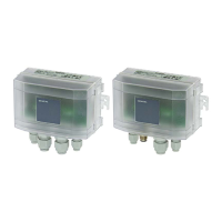
Recommended mounting positions:
• Vertical, with the pressure connections
facing downward, drain off possible
condensed water (factory calibration).
• Horizontal, with the cover facing downward.
• Horizontal, with the cover facing upward.
NOTE: Mount the transmitter with a minimum 0.39
inches (10 mm) distance to magnetic
material. If this is not possible there may be
an error of up to -.004 inch WC for
transmitters mounted on sheet steel.
Figure 3. Wiring Diagram, 4 to 20 mA.
Tubing Connections
Figure 1. Recommended Mounting Positions.
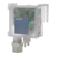
ZP – Push Zero Point Reset
The installation position is variable by using the Zero
Point Reset button. Pressure variations can be reset
after installation.
Ensure the power supply is not interrupted when
storing customer settings (ZP – reset).
Figure 4. High and Low Pressure Connections.
The installation is now complete.
Figure 2. ZP Push Zero Point Reset.
Information in this publication is based on current specifications. The company reserves the right to make changes in specifications and
models as design improvements are introduced. Product or company names mentioned herein may be the trademarks of their respective
owners. © 2013 Siemens Industry, Inc.
Siemens Industry, Inc.
Building Technologies Division
1000 Deerfield Parkway
Buffalo Grove, IL 60089-4513
USA
+1-847-215-1000
Your feedback is important to us. If you have
comments about this document, please send them
to SBT_technical.editor.us.sbt@siemens.com
Document No. 129-903
Printed in the USA
Page 2 of 2
 Loading...