Technical Instructions QVM62.1 Air Velocity Sensor
Document Number 155-006
October 26, 2006
Information in this publication is based on current specifications. The company reserves the right to make changes in specifications and models as
design improvements are introduced. © 2006 Siemens Industry, Inc.
Building Technologies Division
1000 Deerfield Parkway
Buffalo Grove, IL 60089
Your feedback is important to us. If you have
comments about this document, please send them
to sbt_technical.editor.us.sbt@siemens.com
Printed in the USA
Page 4
Mounting and
Installation Notes
Mount the immersion stem so that the air flows through the opening at the sensor head.
The immersion stem is pre-mounted and wired to the transducer on delivery. The
sensor pipes and the end with the direction arrow are prearranged on the connecting
cable; fit them together (use the direction-oriented snap-on connections). If the
extension pipe is not required, remove it from the cable. The connecting flange is not
attached on delivery.
The sensor is supplied with Installation Instructions.
Commissioning
Notes
Check the wiring and air velocity range settings prior to commissioning.
Check the immersion stem position in the air duct (see Installation Instructions).
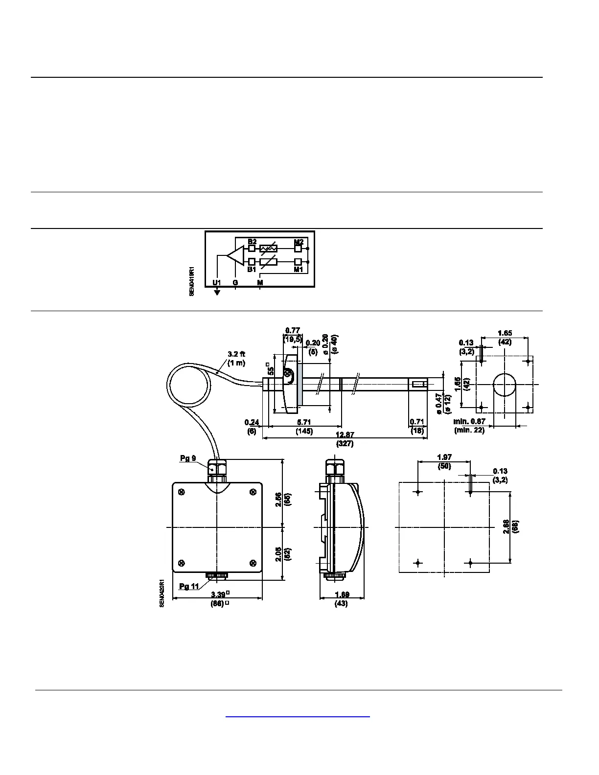
Wiring Diagram
Figure 3. Wiring Diagram.
G 24 Vac operating voltage
M Measuring neutral/operating voltage
ground
U1 0 to 10 Vdc output signal
Dimensions
Figure 4. Dimensions in Inches (Millimeters).
 Loading...


