Installation Instructions
Document No. 129-095
September 24, 2009
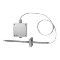
QVM62.1 Air Velocity Sensor
Item Number 129-095, Rev. AA Page 1 of 3
Product Description
This sensor is used to measure the air velocity in a
duct and provide a 0 to 10V signal to a controller
that is proportional to the velocity. This allows the
controller to maintain a constant airflow in the duct,
balance out pressure fluctuations (supply or exhaust
air control), or just monitor the flow in a duct. The Air
Velocity Sensor is generally used for modulating fan
control in primary applications to set the basic
volume flow.
Product Number
QVM62.1
Warning/Caution Notations
WARNING:
Personal injury/loss of life may
occur if you do not follow the
CAUTION:
Equipment damage or loss of
data may occur if you do not
follow the procedures as
Required Tools
• Pencil
• Hammer
• Center hole punch
• Screwdrivers
• Four - #8 × 1/2-inch sheet metal screws
• Electric drill with 1/8-inch and 7/8-inch
drill bits
Expected Installation Time
45 minutes
Prerequisites
Field wiring must be pulled to installation location.
Installation
Probe Mounting Flange and Sensor
1. Determine the depth of insertion required for
the probe and assemble the extension tube
and/or probe end cap onto the primary sensor
head tube.
NOTE: If the insertion depth required is less
than or equal to 5.7 inches (145 mm)
the extension tube may be removed by
disconnecting the probe cable at the
transducer head, and sliding the
extension tube off the cable. (With the
extension tube installed, the probe’s
depth of insertion is 11.8 inches
[300mm].) If the extension tube is
removed, be sure to reinstall the
probe’s end cap on the cable before
rewiring it to the transducer head.
2. Position the probe mounting flange on the duct
where will be installed. Lightly tap the screw
heads to create drill marks for the mounting
screw holes.
NOTE: Install the sensor in the ductwork in a
location where the airflow is not
turbulent. Do not place it close to
dampers, registers, or bends in
ductwork.
Figure 1. Mounting Locations.