EasyManua.ls Logo

Siemens RDF10U

Siemens RDF10U
7 pages
To Next Page IconTo Next Page
Loading...
Installation Instructions
Document No. 129-497
May 18, 2011
RDF Series Room Temperature
Controllers
Item Number 129-497, Rev. BA Page 1 of 7
Product Description
Room Temperature Controllers with LCD for two-
pipe (with and without an electrical heater) and four-
pipe fan coil units.
Product Numbers
Part Number Application
RDF10U Two-pipe fan coil units
RDF20U Two-pipe fan coil units with
electrical heater
RDF30U Four-pipe fan coil units
RDF50.1U Two-pipe fan coil units with 0 to 10
Vdc output
Required Tools
Small, flat-blade screwdriver
Wire strippers
Electric drill
Expected Installation Time
30 minutes
Accessories
141-570 Lockable Thermostat Guard
ARG70 Wall Plate Adapter
QAH11.1 Remote/Changeover Sensor
Installation
Step 1. Loosen retaining screws.
Step 2. Remove controller housing.
Step 3. Mount base plate to wall.
Step 4. Remove screw and open terminal cover.
Question and Answer IconNeed help?

Do you have a question about the Siemens RDF10U and is the answer not in the manual?

Siemens RDF10U Specifications

General IconGeneral
BrandSiemens
ModelRDF10U
CategoryTemperature Controller
LanguageEnglish

Summary

Product Information

Product Description

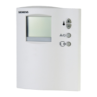
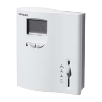
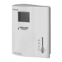
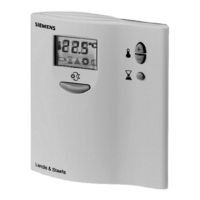
Details the Room Temperature Controllers for two-pipe and four-pipe fan coil units.

Product Numbers

Lists part numbers for RDF controllers and their specific applications.

Required Tools

Specifies the tools needed for installation, such as screwdrivers and wire strippers.

Expected Installation Time

Indicates the estimated time required for controller installation.

Accessories

Lists optional accessories for the RDF controllers, like guards and adapters.

Installation Steps

Step 1: Loosen Retaining Screws

Initial step to loosen screws before removing the controller housing.

Step 2: Remove Controller Housing

Procedure for detaching the controller's outer casing.

Step 3: Mount Base Plate to Wall

Instruction for securing the mounting base plate onto the wall.

Step 4: Remove Screw and Open Terminal Cover

Action to access the terminal connections by removing a screw.

Continued Installation and Wiring

Step 5: Terminate Wires

Guide for connecting wires to terminals, referring to wiring diagrams.

Step 6: Set DIP Switches

Instructions for configuring the controller's DIP switches.

Step 7: Replace Controller Housing

Procedure for reattaching the controller casing after wiring.

Step 8: Tighten Retaining Screws

Final step to secure the controller housing with retaining screws.

Wiring Diagrams

Controller Dimensions

Operating Instructions Overview

Display Information

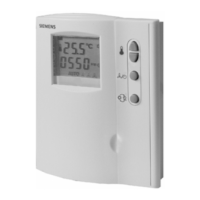
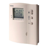
Explains the controller's display elements for temperature and status.

Normal Operation

Describes basic operations like adjusting temperature setpoints using +/- buttons.

Mode Transitions

Covers changing between Heating, Cooling, Standby, and Economy modes.

Economy Mode Settings

Control Parameter Adjustment

Sensor Recalibration

DIP Switch Settings

Commissioning Parameters

Related product manuals