Document No. 129-497
Installation Instructions
May 18, 2011
S1
B2
B1
M1
Y1
I
II
III
SN
SP
SN
1
39 8 7 D1GND
42101112
N1
E1
65
TH0901R1
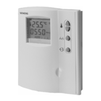
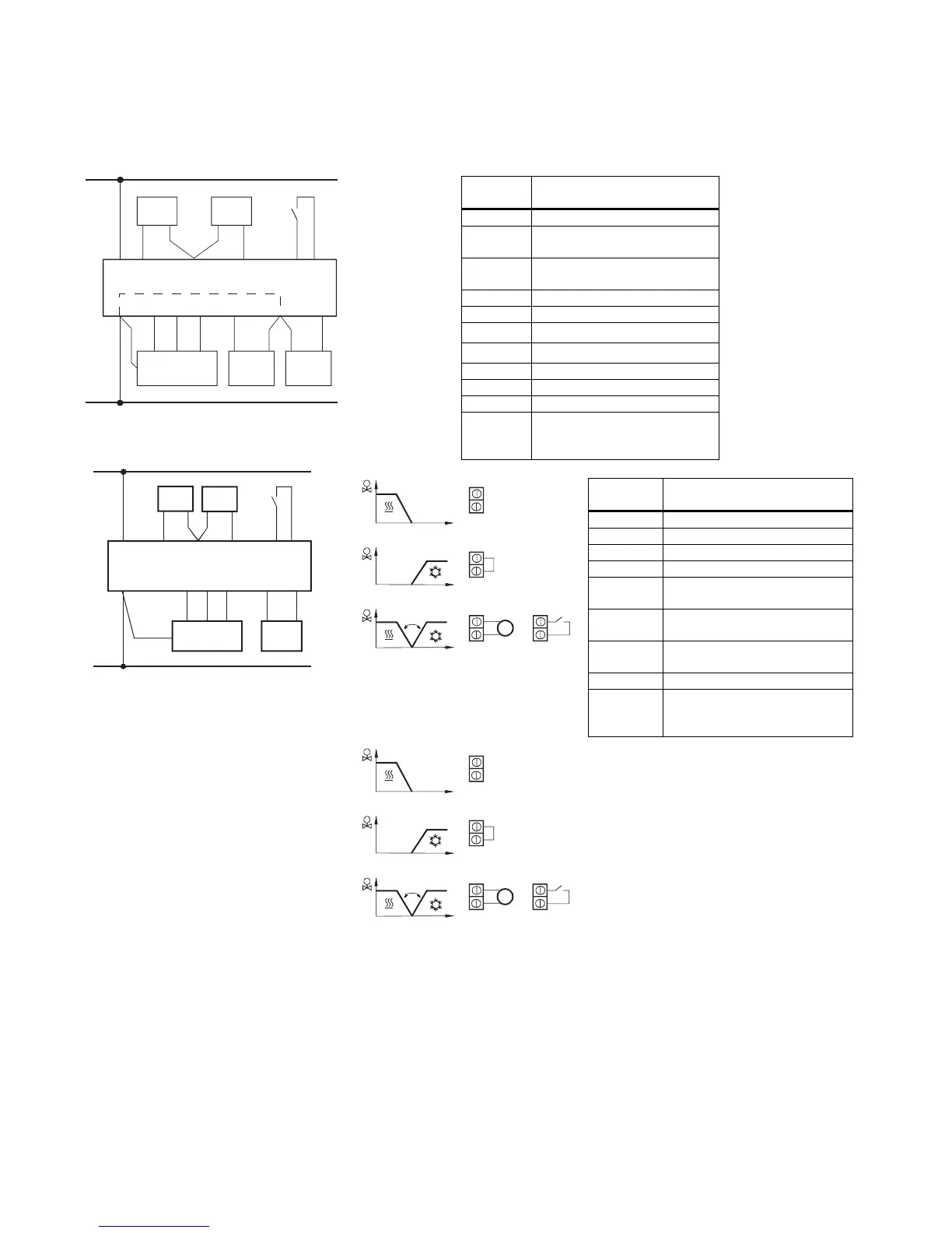
Figure 3. RDF20U.
Terminal
Position
RDF20U Terminal Function
1 Ground for control signal
2 Operating voltage 24 Vac
negative
3 Operating voltage 24 Vac
positive
4 Heating/cooling output NO
5 Heating/cooling output NC
6 Electric heater output NO
7 Heat/Cool changeover sensor
8 Measuring Neutral
9 Remote air sensor
10,11, 12 Fan speed output III, II, I
D1,
GND
Signal input for potential-free
operating mode changeover
switch
TH0896R1
S1
B2
M1
Y1
I
II
III
SN
SP
SN
5
723D1
Siemens Industry, Inc. Page 3 of 7
G
16
N1
101112
ND
B1
4
Figure 4. RDF50.1U.
3
2
T F
3
2
3
2
T
3
2
QAH11.1
T F
T F
TH0890R1
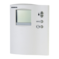
Figure 5. RDF50.1U.
Terminal
Position
RDF50.1U
Terminal Function
1 0 to 10 Vdc output for valve
2 Heat/Cool changeover sensor
3 Measuring neutral
4 Return air sensor
5 Operating voltage 24 Vac,
negative
6 Operating voltage 24 Vac,
negative
7 Operating voltage 24 Vac
positive
10,11,12 Fan speed output III, II, I
D1,
GND
Signal input for potential-free
operating mode changeover
switch
T F
7
8
7
8
7
8
T
7
8
QAH11.1
T F
T F
TH0900R1
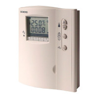
Figure 7. RDF10U, and
RDF20U.
 Loading...