Document No. 129-497
Installation Instructions
May 18, 2011
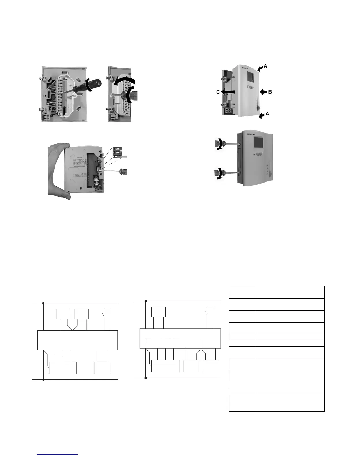
Installation, Continued
Step 7. Replace controller housing.
Step 5. Terminate wires (see wiring diagrams),
close cover terminal cover and replace screw.
Step 8. Tighten retaining screws.
Step 6. Set DIP switches.
The installation is now complete.
Wiring Diagrams
B1 Remote temperature sensor
B2 Changeover sensor
E1 Electric heat
M1 Three-speed fan motor
S1 Digital input for day/night changeover
Y1 Control valve, heat/cool or two-pipe system
Y2 Cooling control valve for four-pipe system
TH0899R1
S1
M1
Y1
III
III
SN
SP
SN
1
3
7
8
D1 GND
42101112
N1
9
B2B1
5
Figure 1. RDF10U.
TH0897R1
S1 B1
M1
1
I
II
III
SN
SP
SN
1
39 8 D1 GND
42101112
N1
2
6
5
Figure 2. RDF30U.
Terminal
Position
RDF10U and RDF30U
Terminal Function
1 Operating voltage 24 Vac
negative
2 Operating voltage 24 Vac
negative
3 Operating voltage 24 Vac
positive
4 Heating/cooling output NO
5 Heating/cooling output NC
6 Second stage Heating/Cooling
output NO (RDF30U only)
7 Heat/Cool changeover sensor
(RDF10U only)
8 Measuring Neutral, remote or
changeover sensor
9 Remote air sensor
10,11, 12 Fan Speed output III, II, I
D1,
GND
Signal input for potential-free
operating mode changeover
switch
Page 2 of 7 Siemens Industry, Inc.
 Loading...