11 / 40
Siemens RDF300…/RDF340.../RDF400… Basic Documentation CE1P3076en
Building Technologies 4BFunctions 28 Aug 2008
4.4 Applications
The controller supports following applications, which can be configured by DIP-
switches on the inner side of the controller front panel. Depending on the type,
on/off or modulating control outputs are available.
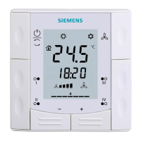
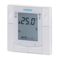
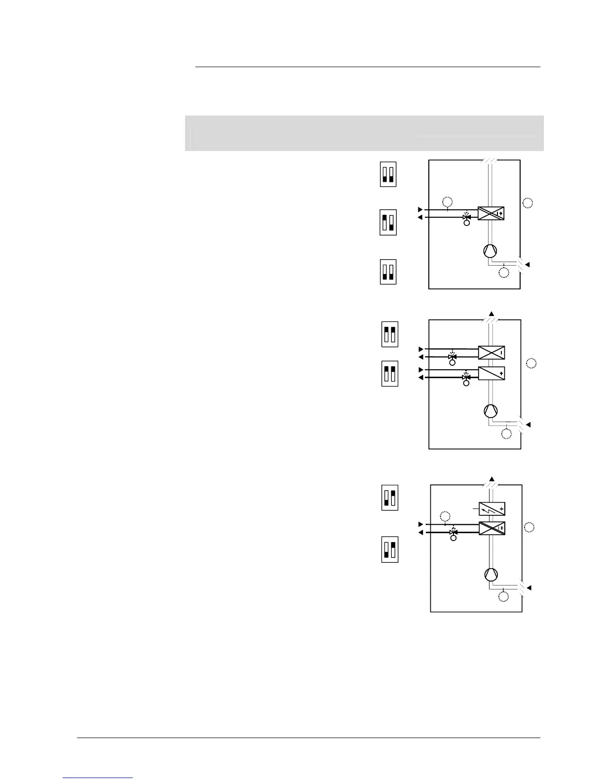
Note: The diagrams above show only the water based fan coil application, but not compressor!
Application and
Control output
Type
reference
DIP-
switch
Diagram
2-pipe fan coil unit,
heating and cooling
2-pipe/1-stage compressor
on/off
RDF300
RDF400
ON
1 2
2-pipe
modulating, 3-position
RDF300
RDF400
ON
1 2
2-pipe
modulating, DC 0…10 V
RDF340
ON
1 2
3076D20
(B1)
M1
Y1
T
B2
T
T
(B1)
4-pipe fan coil unit,
heating and cooling
4-pipe/compressor for H+C
on/off
RDF300
RDF400
ON
1 2
4-pipe modulating,
DC 0…10 V
RDF340
ON
1 2
T
Y2
Y1
M1
3076D22
(B1)
T
(B1)
2-pipe fan coil unit
with electrical heater,
heating or cooling with
auxiliary heater
2-pipe/1-stage compressor
with electrical heater on/off
RDF300
RDF400
ON
1 2
2-pipe with electrical heater
modulating, DC 0…10 V
Note: Modulating electrical heater
RDF340
ON
1 2
Y1
M1
3076D21
T
B2
E1
T
(B1)
T
(B1)
Key Y1 Heating or heating/cooling valve actuator M1 3-speed or single-speed fan
Y2 Cooling valve actuator B1 Return air temperature sensor or
external room temperature sensor (optional)
E1 Electrical heater B2 Changeover sensor (optional)

 Loading...