7 / 12
Siemens Semi-flush-mount Room Thermostats with LCD CB1N3064en
Building Technologies 24.08.2010
Mechanical design
The controller consists of 2 parts:
• Front panel which comprised by the electronics, the operating elements and the
built-in room temperature sensor
• Mounting base with the power electronics
The rear of the mounting base contains the screw terminals which fit on a rectan-
gular conduit box with fixing centres 60.3 mm. The front panel engages in the
mounting base and snaps on.
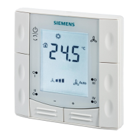
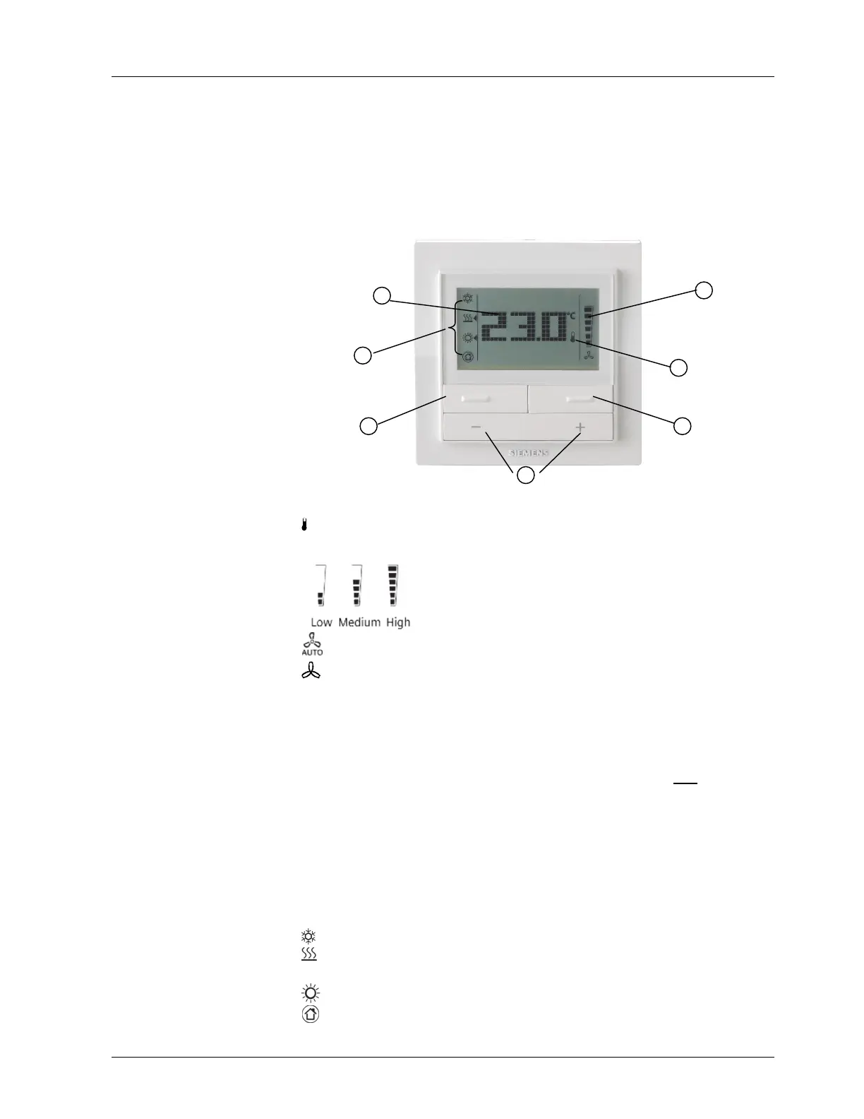
① Display of the room temperature, setpoints and control parameters
② Symbol used when displaying the current room temperature
③ Fan mode and fan speed indicator
Automatic fan active
Manual fan active
④ Fan mode button
− changing the fan mode (Auto/manual)
−
changing the fan speed (Low/Medium/High)
⑤ Heat/Cool mode selector
− For the changeover between cooling mode and heating mode if P22 = 3
Or: Operating mode button
− For the selection of comfort mode and protection mode
Or: Button lock
− Press and hold for 7 seconds, to locked and unlocked the buttons manually
⑥ Buttons for adjusting the setpoints and control parameters
⑦ Mode indicator
Heat/Cool Mode indicator:
Cooling mode active
Heating mode active
Operating Mode indicator:
Comfort mode active
Protection mode active
Setting and operat-
ing elements
Legend:
 Loading...