17/23
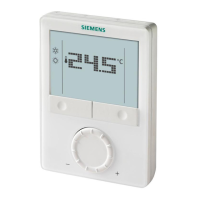
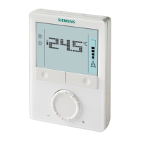
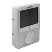
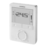
Siemens RDG1... Wall-mounted room thermostats with LCD CE1N3181en
Building Technologies 2017-11-20
Degree of protection of housing IP30 to EN60529
The product environmental declaration CE1E3181
*)
and CE1E3181_1
*)
contains data
on environmentally compatible product design and assessments (RoHS compliance,
materials composition, packaging, environmental benefit, disposal).
Connection terminals Solid wires or prepared stranded
1 x 0.4…2.5 mm
2
(14 gauge)
or 2 x 0.4…1.5 mm
2
(16 gauge)
Note: For sensors on inputs X1, X2, or D1, the cable length is max. 80 m (262 feet).
Wiring cross section on
L, N, Q1, Q2, Q3, Y1, Y2, Y3, Y4, Y11, Y21
Min. 1.5 mm
2
(16 gauge)
Housing front color RAL 9003 white
Weight RDG100../RDG110..
RDG160T..
0.30 kg
0.32 kg
*)
The documents can be downloaded from http://siemens.com/bt/download.
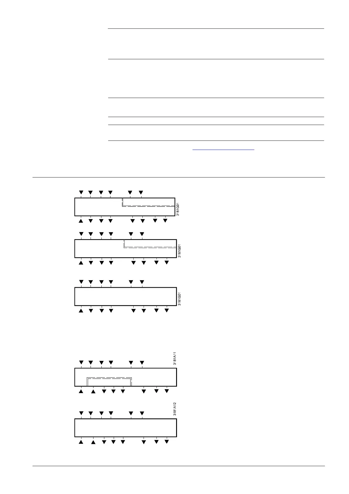
Connection terminals
RDG100,
RDG100T,
RDG100T/H
N Q1 Q2 Q3 Y1 Y2 Y3 Y4
SE LV
L, N Operating voltage AC 230 V
G, G0 Operating voltage AC/DC 24 V
Note: For DC 24 V: G0 = –; G = +
X1, X2 Multifunctional input for temperature sensor
(e.g. QAH11.1) or potential-free switch
Factory setting :
- X1 = external room temperature sensor
- X2 = sensor or switch for heating/cooling
changeover
Change of setting: Parameters P38, P40
M Measuring neutral for sensor and switch
D1, GND Multifunctional input for potential-free switch.
Factory setting: Operating mode switchover
contact
Change of setting: Parameter P42
Q1 Control output fan speed "low"
Q2 Control output fan speed "medium"
Q3 Control output fan speed "high"
Y1…Y4 Control output "Valve" AC 230 V
(NO, for normally open valves),
output for electric heater via external relay
Y11, Y21 Control output "Valve" AC 230 V for RDG110
Control output "Valve" AC 24 V for RDG110U
(NO, for normally open valves),
output for compressor or electric heater
Y12, Y22 Control output "Valve" AC 230 V for RDG110
Control output "Valve" AC 24 V for RDG110U
(NC, for normally closed valves)
G, G0 Operating voltage AC/DC 24 V
Note: For DC 24 V: G0 = –; G = +
L (-N) Power supply relay output Q1…3 AC 24…230 V
for RDG160T
Y10, Y20 Control output for DC 0…10 V actuator
Y50 Control output "Fan" DC 0...10 V
Q1 … 3 Control output fan, valve, el. heater or ex.
equipment
C (-G0) Power supply relay output Q1…3
AC 24 V for RDG160TU
RDG110
N Q1 Q2 Q3 Y11 Y12 Y21 Y22
RDG110U
SE LV
G0 Q1 Q2 Q3 Y11 Y12 Y21 Y22
RDG160T
G0 L Q1 Q2 Q3 Y50 Y10 Y20
RDG160TU
G0 C Q1 Q2 Q3 Y50 Y10 Y20
Environmental
Compatibility
General

 Loading...