7/12
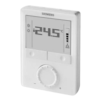
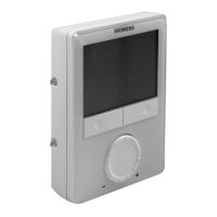
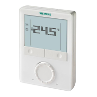
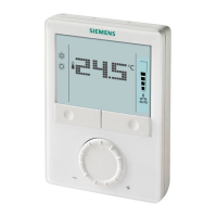
Siemens RDG1… room thermostats N3181en
Building Technologies May 28. 2009
Mounting and installation
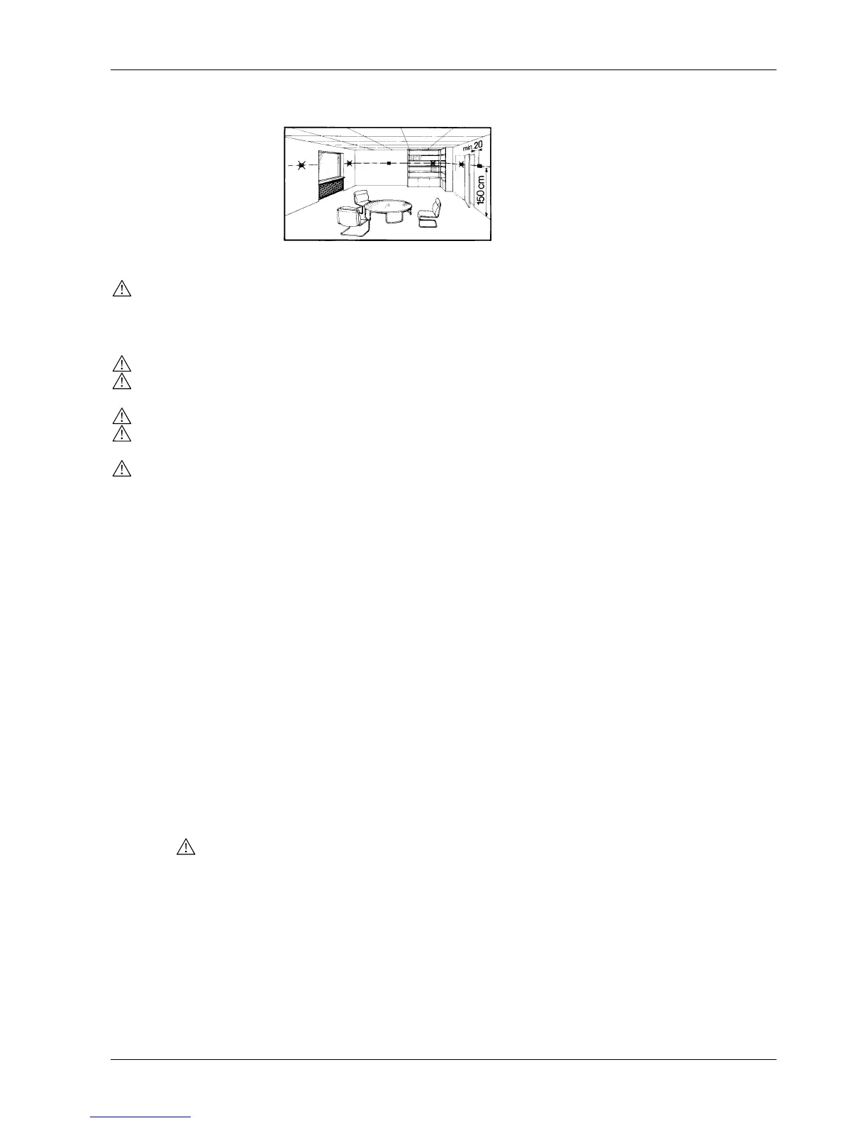
Do not mount on a wall in niches or bookshelves, behind curtains, above or near heat
sources, or exposed to direct solar radiation. Mount about 1.5 m above the floor.
• The room thermostat must be mounted in a clean, dry indoor place and must not be
exposed to drip or splash water
See Mounting Instructions (M3181) enclosed with the thermostat.
• Comply with local regulations to wire, fuse and earth the thermostat
• Size correctly the cables to the thermostat, fan and valve actuators for AC 230 V
mains voltage
• Use only valve actuators rated for AC 230 V on RDG100… / RDG110
• The power supply line must have an external fuse or circuit breaker with a rated
current of no more than 10 A
• Isolate the cables of inputs X1-M / X2-M and D1-GND if the conduit box carries
AC 230 V mains voltage
• On the RDG100.. and RDG110, inputs X1-M and X2-M carry mains potential.
If the sensor’s cables are extended, they must be suited for mains voltage
• Inputs X1-M, X2-M or D1-GND of different units (e.g. summer / winter switch) may
be connected in parallel with an external switch. Consider overall maximum contact
sensing current for switch rating
• Disconnect power supply before removing the thermostat from the mounting plate!
Select the application and the type of control output via the DIP switches before fitting
the thermostat to the mounting plate.
After power is applied, the thermostat carries out a reset during which all LCD
segments flash, indicating that the reset was correct. After the reset, which takes about
3 seconds, the thermostat is ready for commissioning by qualified HVAC staff.
The control parameters of the thermostat can be set to ensure optimum performance of
the entire system (see Basic Documentation P3181).
• The control sequence may need to be set via parameter P01 depending on the
application. The factory setting for the 2-pipe application is “Cooling only”; and
“Heating and cooling” for the 4-pipe application
• When the thermostat is used in connection with a compressor, the minimum output
on-time (parameter P48) and off-time (parameter P49) for Y11/Y21 must be
adjusted to avoid damage to the compressor and shortening its life
• Recalibrate the temperature sensor if the room temperature displayed on the
thermostat does not match the room temperature measured. To do this, change
parameter P05
• We recommend to review the setpoints and setpoint ranges (parameters P08…P12)
and change them as needed to achieve maximum comfort and save energy
Mounting
Wiring
Commissioning
Control sequence
Compressor-based
application
Calibrate sensor
Setpoint and setpoint
range limitation

 Loading...