Siemens Building Technologies / HVAC Products CE1G3332hu 06.09.2002 3/8
en
English
Mounting
Place of installation
• As an extract air temperature controller:
In the extract air duct directly after the air intake from the
room, or in the common duct in the case of several air
intakes. Always upstream of the extract air fan
• As a supply air temperature controller:
−
In the supply air duct downstream from the supply air
fan if fan is installed after the last air handling unit,
otherwise
−
In the supply air duct downstream from the last air
handling unit in a distance of 0.5 m
• As a minimum supply air temperature limiter:
In the supply air duct as close as possible to the air dis-
charge into the room
• As a dewpoint controller:
Immediately downstream from the droplet separator of
the air washer
Mounting
Procedure:
1. First mount the flange. For drilling holes, refer to “Di-
mensions”.
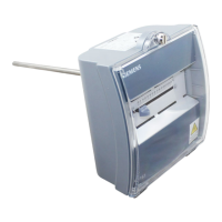
2. Bend flexible sensing element manually (never use a
tool) so that – when mounted – it stretches diagonally
across the air duct .
Note! The flexible sensing element may not touch the
duct wall: The minimum clearance is 50 mm and the
smallest permissible bending radius 10 mm
3. Fit mounting flange.
4. Slide controller on mounting flange and snap it on.
Electrical installation
• Ensure that the local regulations for electrical installa-
tions are complied with
• The connecting terminals are located under the flexible
plastic cover
• Make wiring according to the plant documentation. If not
available, use the connection diagrams contained in
these Installation Instructions
• Observe the permissible cable lengths
• Switch on power only when commissioning the controller
Settings
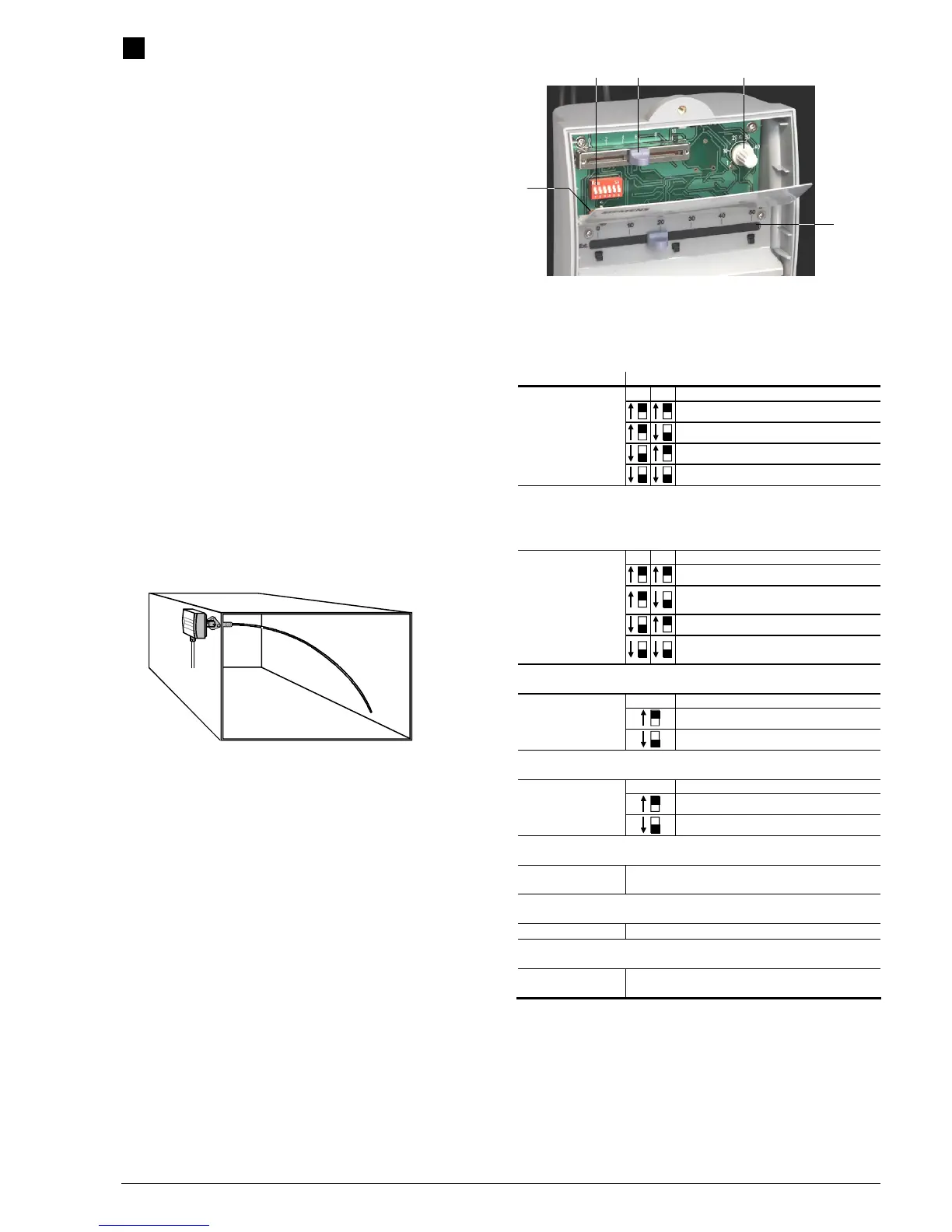
1
5
2 3 4
3332P01
1 LED for test mode / normal operation
2 DIP switch block
3 Setting slider for setpoint increase or decrease
4 Potentiometer for P-band
5 Temperature setting slider for setpoint or limit value
Operating action:
Where? What?
1 2
Heating and cooling in sequence
Single-stage cooling
DIP switch block,
switches no. 1 and 2
Single-stage heating
Control mode and integral action time:
3 4
PI mode, integral action time = 600 s
(SLOW)
PI mode, integral action time = 120 s (FAST)
DIP switch block,
switches no. 3 and 4
PI mode, integral action time = 180 s
(MEDIUM)
Test mode:
5
Test mode
DIP switch block,
switch no. 5
Normal operation
Outside temperature compensation:
6
HIGH
DIP switch block,
switch no. 6
LOW
P-band Y1 (not adjustable for Y2):
Potentiometer 4 Potentiometer setting should correspond to the required
range of the controller’s output signal
Setpoint increase / decrease:
Slider 3
Setpoint or limit value (supply or extract air temp.):
Temperature setting
slider 5
Adjust after commissioning
Indication of operating state
The red LED indicates the controller’s operating state:
• LED lit: Mains voltage present
• LED flashes: In test mode
The LED is also visible when the cover is fitted.