4/8 06.09.2002 CE1G3332hu Siemens Building Technologies / HVAC Products
Commissioning
When used as a controller
1. Remove housing cover.
2. Lift flexible plastic cover so that you can access the
setting elements.
3. Make the settings:
−
Operating action (DIP switches 1 and 2)
−
Control mode and (with PI mode) integral action
time (DIP switches 3 and 4)
−
Test mode: (DIP switch no. 5 =
)
−
Outside temperature compensation, when using an
outside sensor (DIP switch no. 6)
−
P-band Y1 (potentiometer 4)
−
Setpoint increase or decrease (slider 3)
4. Replace flexible plastic cover.
5. Switch power on. LED for the operating state must
flash (test mode).
6. First, set temperature setting slider to the minimum
value, then to the maximum value: Actuating device(s)
must travel to the minimum or maximum position.
If response is wrong, refer to “Troubleshooting”
7. Switch power off.
8. Switch controller to normal operation (DIP switch no.
5 to ).
9. Switch power on. LED for the operating state must
light up (normal operation).
10. If used, activate the auxiliary functions (setpoint
changeover, load-dependent switching contact, etc.).
11. If a remote setting unit is used, set the controller’s
slider for the supply or extract air temperature setpoint
as follows:
−
To EXT, if setpoint shall be adjusted with the remote
setting unit
−
To the required setpoint, if the remote setting unit
shall only be used for setpoint readjustments
12. First, set temperature setting slider to the minimum
value, then to the maximum value: Observe the con-
trol. The response may neither be too fast nor too
slow
If response is wrong, refer to “Troubleshooting”
13. Adjust the setpoint with the temperature setting slider.
14. Replace housing cover.
When used as a supply air temperature limiter
1. Switch on the room or extract air temperature control.
2. Remove housing cover.
3. Lift flexible plastic cover so that you can access the
setting elements.
4. Make the settings:
−
Operating action: Single-stage heating
Switch no. 1 = , switch no. 2 =
−
Control mode: P (sSwitch no. 3 = , switch no. 4 =
)
−
Test mode: Switch no. 5 =
−
P-band Y1 on approx. 25 K
5. Replace housing cover.
6. Switch power on. LED for the operating state must
flash (test mode).
7. Set temperature setting slider on the limiter to the
maximum value:
Controller must demand a temperature increase
(heating valve must open or cooling valve must close)
If response is wrong, refer to “Troubleshooting”
8. Switch power off.
9. Remove housing cover.
10. Switch limiter to normal operation (set switch no. 5 to
).
11. Replace housing cover.
12. Adjust limit value with the temperature setting slider.
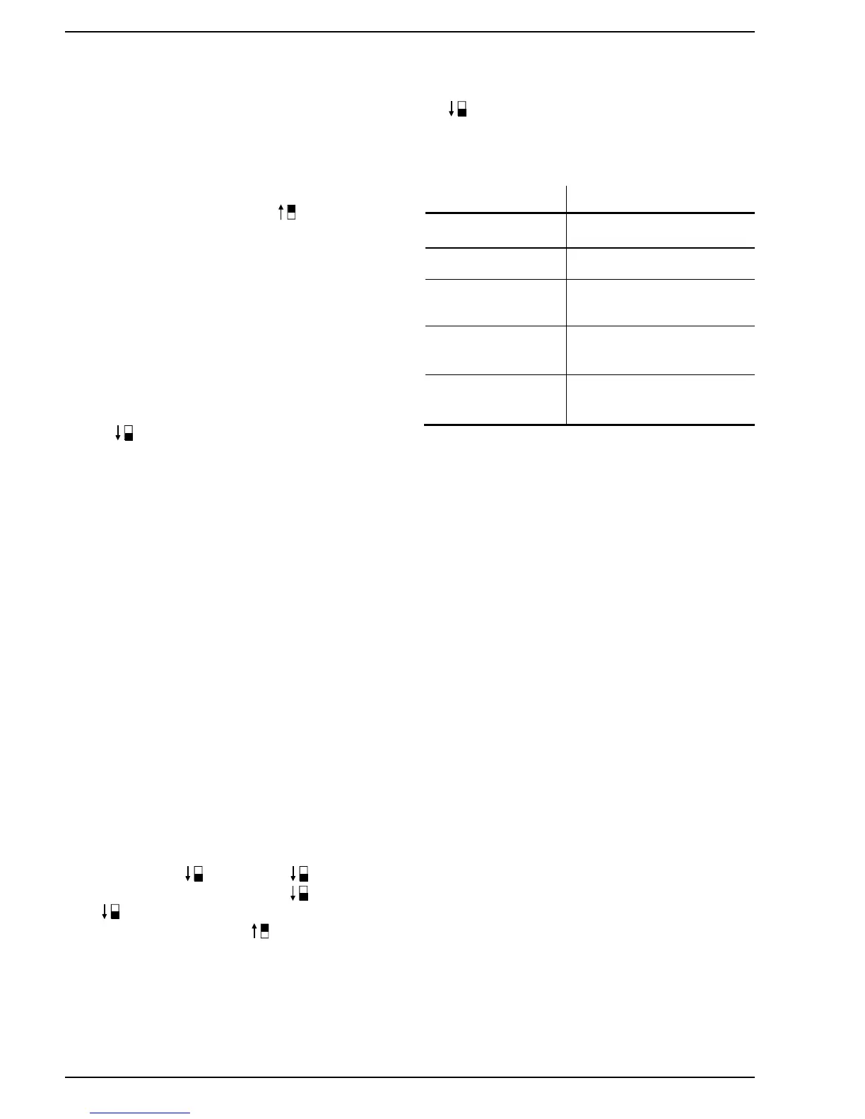
Troubleshooting
Wrong response Possible causes
Valve does not re-
spond
• Valve not connected
• No power supply
Valve travels in the
wrong direction
Selection of operating action is
wrong
Valve remains in one of
the end positions
Temperature setting slider is
set to EXT and there is no
remote setting unit connected
Control responds too
slowly
• Reduce P-band
• With PI mode, also reduce
the integral action time
Control is instable
• Increase P-band
• With PI-mode, also increase
the integral action time
 Loading...