14/24 2019-05-16 CE1G3101x1 74 319 0428 0 D Siemens Smart Infrastructure
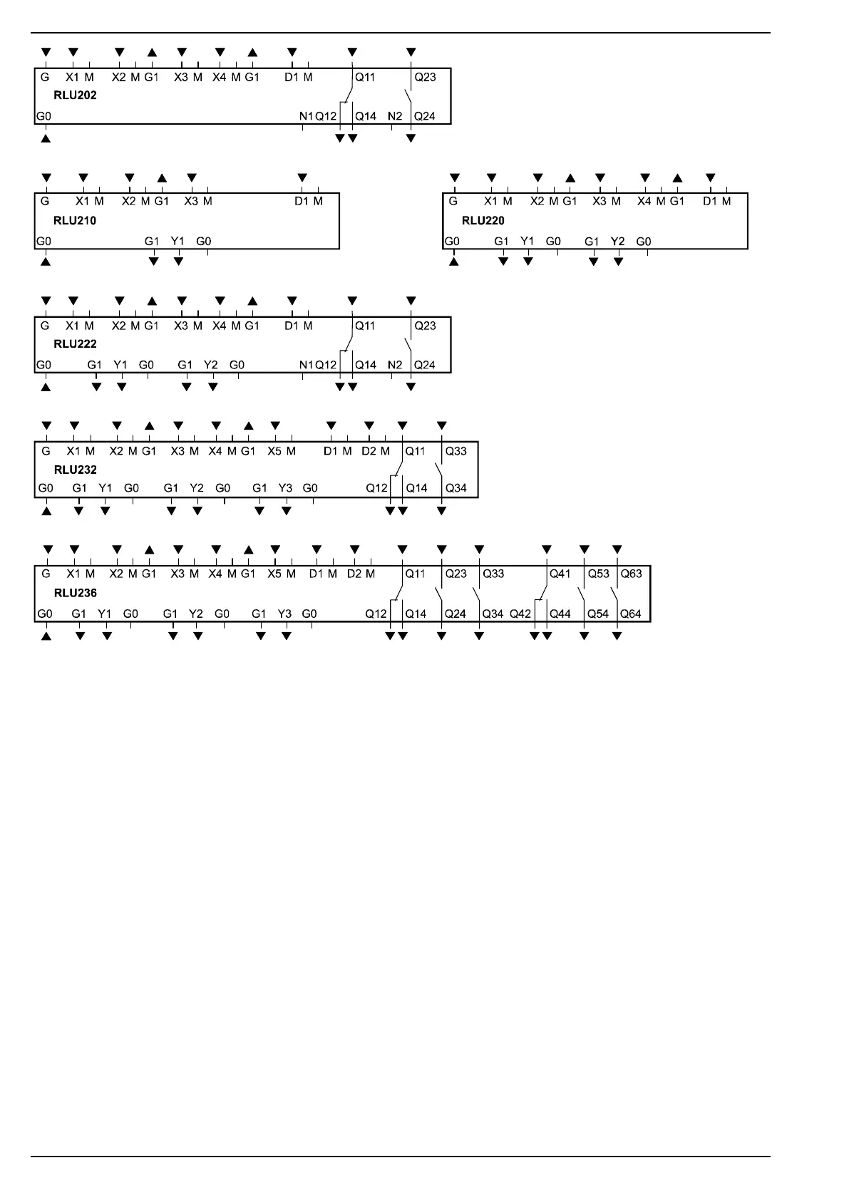
Legend
G, G0
G1
M
G0
X…
X…, D…
Y…
Q…
N1, N2
Rated voltage AC 24 V
Output voltage AC 24 V for powering external active sensors, signal sources, monitors or setting units
Measuring neutral for signal input
System neutral for signal output
Universal signal inputs for LG-Ni 1000, 2x LG-Ni 1000 (averaging),
T1, Pt 1000, DC 0...10 V, 0...1000 W (= REM), 1000…1175 W (= REL)
Contact sensing (potential-free)
Control or status outputs, analog DC 0...10 V
Potential-free relay outputs for AC 24...230 V
Neutral conductor connection for radio interference suppression elements
Legende
G, G0
G1
M
G0
X…
X…, D…
Y…
Q…
N1, N2
Bemessungsspannung AC 24 V
Ausgangsspannung AC 24 V zur Speisung externer aktiver Fühler, Melder, Wächter oder Geber
Messnull für Signaleingang
Systemnull für Signalausgang
Universal-Signaleingänge für LG-Ni 1000, 2x LG-Ni 1000 (Mittelwertbildung),
T1, Pt 1000, DC 0...10 V, 0...1000 W (= REM), 1000…1175 W (= REL)
Kontaktabfrage (potentialfrei)
Steuer- oder Meldeausgänge, analog DC 0...10 V
potentialfreie Relaisausgänge für AC 24...230 V
Nullleiteranschluss für Funk-Entstörglieder

 Loading...