Siemens Industry, Inc.
Building Technologies Division
P/N 315-033270-122
OPERATION When a system event occurs, the PMI/PMI-2/PMI-3 (XLS), FCM2041-U2 (Desigo Fire
Safety Modular), FCM2041-U3 (Cerberus PRO Modular) sends a print message to the
RPM via HNET. The RPM is responsible for printing the message. The RPM contains a
buffer to ensure that events that occur at a rate faster than the PAL-1 can print them are
not lost.
If the FSI option is selected (via
Zeus) the same event is sent to
the FSI port. This event remains
in a buffer until the Foreign
System removes it.
The RPM continuously moni-
tors the connection to the PAL-
1 checking for any errors that
would inhibit printing. Any
errors that are detected are
communicated to the PMI/PMI-
2/PMI-3 (XLS), FCM2041-U2
(Desigo Fire Safety Modular),
FCM2041-U3 (Cerberus PRO
Modular) via HNET for annun-
ciation. Restoration to the
normal condition is also
detected and communicated to
the PMI/PMI-2/PMI-3 (XLS),
FCM2041-U2 (Desigo Fire
Safety Modular), FCM2041-U3
(Cerberus PRO Modular). Print
messages that arrive at the RPM
during a printer fault are stored in the buffer.
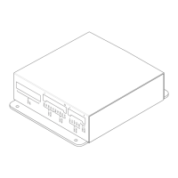
Controls and Indicators The HNET side panel of the RPM contains one reset switch, three LEDs, one termina-
tion switch and one HNET address switch as shown in Figure 2.
A reset switch is located on the top of the panel.
Pushing the reset switch
re-initializes the RPM
operation.
POWER (Green) Normally ON. When illuminated, indi-
cates that power for the RPM is applied
to the module.
CPU FAIL (Yellow) Normally OFF. When illuminated, indi-
cates that the module microprocessor
has failed.
HNET FAIL (Yellow) Normally OFF. When illuminated, indi-
cates that the HNET communication with
the RPM has terminated.
A three-position switch located directly beneath the LEDs on the HNET side of the
RPM is used to set the HNET network address of the RPM.
PORT 3
SPP
PORT 1
RS-232
11
10 7
RXD
TXD
GND
RTS
CTS
RXD
TXD
GND
RTS
CTS
RCV+
RCV-
XMIT+
XMIT-
GND
PORT 3
RS-232
PORT 2
RS-485
PORT 2
SELECT
PRINTER SIDE
6
5
4
3
3
CHASSISGND
24V INPUT
2
1
-
+
2
1
HNET
HNET ADDRESS
TERMINATION
ON
RESET
POWER
CPUFAIL
HNET FAIL
+
-
+
-
+
-
HNET SIDE
Figure 2
RPM Side Panel Detail
 Loading...
