Siemens Industry, Inc.
Building Technologies Division
P/N 315-033270-127
NOTES:
1. 14-18 AWG. Twisted pair or
twisted shielded pair.
2. Must be connected within
the same room.
3. Power Limited to NFPA 70
per NEC 760.
4. Maximum Voltage 8V peak
to peak.
5. Maximum Current 150mA.
6. Optional supervision
(selected in Zeus) (2 wire
only).
7. Foreign System must be UL
EDP or ETI listed.
8. A 120 ohm EOLR is
internally connected to Port
2 terminals 1 and 2.
9. Only ONE FSI (RS-232 or
RS-485) connection allowed
per RPM.
Figure 11
FSI RS-485 Connection
1
2
1
+
+
-
-
2
3
4
5
6
7
DO NOT USE
FOREIGN
SYSTEM
TXD
RXD
OPTIONAL
SHIELD
PORT2
1) 120 ohm EOLR
2) Connect shield at one end
only.
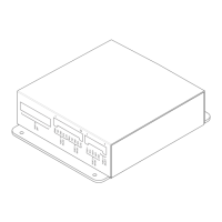
INSTALLATION The RPM mounts with two flanges on the side of the terminal block covers. Select a
smooth surface within 6 feet of the PAL-1 for the RPM.
Position the RPM and attach it to the mounting surface using the four #6 self tapping
screws provided.
Install the terminal block covers using the 6 remaining #10 nuts. Refer to Figure 3.
ELECTRICAL RATINGS
tnerruCenalPkcaBV420
tnerruCV42lanimreTwercS.xaMAm051
tnerruCenalPkcaBV2.60
tnerruCybdnatSV42.xaMAm051
rewoPt
uptuO
riaPkrowteNNAC
.xamkaepotkaepV8
.xamAm57
)noissimsnartgsmgnirud(
 Loading...
