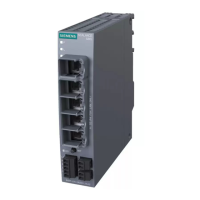
NAT_S615
Entry ID: 109744660, V1.1, 08/2017
Siemens AG All rights reserved
2.3 PG functions with NETMAP and destination NAT
Starting situation
Without a gateway, the PC is to use STEP 7 PG functions on multiple CPUs. STEP
7 PG functions run on an S7 connection with a destination port, TCP 102, that
cannot be changed.
Figure 2-6
VLAN2: 192.168.1.0/24
VLAN1: 192.168.2.0/24
CPU: 192.168.2.20
Gateway: 192.168.2.1
PC:
192.168.1.10
Gateway:
None
192.168.2.1
192.168.1.1
SRC IP:
192.168.1.10
DST IP:
192.168.1.2
SRC IP:
192.168.1.10
DST IP:
192.168.2.20
NAT Table
CPU: 192.168.2.30
Gateway: 192.168.2.1
SRC IP:
192.168.1.10
DST IP:
192.168.1.3
SRC IP:
192.168.1.10
DST IP:
192.168.2.30
Additional IP:
192.168.1.2
192.168.1.3
Requirements
For network separation, the SCALANCE S615 has two VLANs with different
network IDs. As a result, the device has a separate IP address for each VLAN
(in this document: VLAN1: 192.168.2.1 and VLAN2: 192.168.1.1).
To translate the PC’s message frames to a different IP address, a NAT table is
additionally defined in the SCALANCE S615. This requires two other IP addresses
from the subnet of VLAN2 that are not in use.
For the reply packets of the two CPUs to find their way to VLAN2, the IP address of
the SCALANCE S615 (VLAN1) must be entered in the two CPUs as the gateway.
 Loading...
