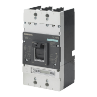
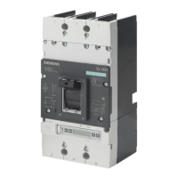
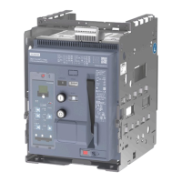
3VL IEC molded case circuit breakers
System Manual, 11/2013, 110 0110 - 02 DS 03
5
1 About this document ............................................................................................................................. 11
1.1 Introduction .................................................................................................................................. 11
1.2 Technical Support ........................................................................................................................ 11
2 Product-specific information .................................................................................................................. 13
2.1 Important notes ............................................................................................................................ 13
2.2 Ordering data ............................................................................................................................... 15
3 Product description ............................................................................................................................... 17
3.1 Overview 3VL ............................................................................................................................... 17
3.2 Application overview .................................................................................................................... 20
3.3 Configuration ................................................................................................................................ 22
3.3.1 Functional principle ...................................................................................................................... 22
3.3.2 Subdivision according to power ranges ....................................................................................... 22
3.3.3 Thermal-magnetic overcurrent trip units ...................................................................................... 23
3.3.4 Electronic overcurrent trip unit (ETU)........................................................................................... 24
3.4 Mechanical operating mechanisms.............................................................................................. 26
3.4.1 Toggle lever operating mechanism .............................................................................................. 26
3.4.2 Rotary mechanism on front (optional) .......................................................................................... 27
3.4.3 Door-coupling rotary operating mechanism (optional) ................................................................. 29
3.4.4 Side panel rotary operating mechanism (optional) ...................................................................... 30
3.5 Motorized operating mechanisms (optional) ................................................................................ 32
3.5.1 Motorized operating mechanism with stored energy mechanism (SEO)..................................... 33
3.5.2 Motorized operating mechanism (MO) ........................................................................................ 34
4 Functions .............................................................................................................................................. 35
4.1 Protection functions ..................................................................................................................... 35
4.1.1 Overcurrent release ..................................................................................................................... 35
4.1.2 Function overview of the overcurrent release .............................................................................. 36
4.1.3 Setting options of the overcurrent release ................................................................................... 38
4.1.4 General technical data of the overcurrent release ....................................................................... 40
4.1.5 Differential current protection with RCD module .......................................................................... 44
4.1.6 Single-pole operation with RCD module ...................................................................................... 48
4.1.7 Ground-fault protection ................................................................................................................ 49
4.2 Internal accessories ..................................................................................................................... 51
4.2.1 Possible complements for the insulated accessory compartments ............................................. 51
4.2.2 Undervoltage release ................................................................................................................... 52
4.2.3 Shunt release ............................................................................................................................... 53
4.2.4 Auxiliary switches and alarm switches ......................................................................................... 54

 Loading...


