Do you have a question about the Siemens SENTRON 3VL and is the answer not in the manual?
Explains the manual's purpose and target audience.
Covers product validity, standards compliance, and liability disclaimer.
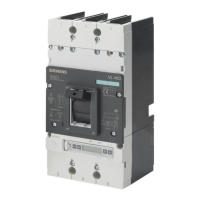
Provides a general overview of SENTRON VL circuit breakers and their types.
Details common applications for SENTRON VL circuit breakers.
Explains functional principles, current limiting, and subdivisions by power ranges.
Describes toggle handle, rotary, and door-coupling rotary operating mechanisms.
Lists potential applications for SENTRON VL circuit breakers.
Presents comprehensive technical data.
Explains overcurrent trip units and their types.
Details voltage protection functions like undervoltage and shunt releases.
Covers the combination of circuit breakers with frequency converters.
Explains the application of circuit breakers for motor protection.
Provides guidance on using circuit breakers in harsh environments and derating factors.
Overviews different installation methods: fixed, plug-in, and withdrawable.
Details mounting positions and safety clearances.
Explains locking devices for mechanisms.
Covers connection methods using cables and busbars.
Describes main conductor connections for fixed-mounted versions.
Details connection methods for plug-in and withdrawable versions.
Lists positions and functions of separate terminals.
Explains setting options for trip units without LCD.
Details features and settings for LCD-equipped trip units.
Covers setting parameters for ETUs and characteristic curves.
Guides on setting motor protection parameters.
Outlines maintenance intervals, inspection steps, and safety precautions.
Provides guidance on resolving common circuit breaker issues.
Lists operating data, dimensions, tripping methods, and capacities.
Details terminal configurations and dimensions.
Presents switching capacities for various applications.
Provides derating factors for altitudes, ambient temperatures, and trip unit types.
Lists characteristic values for motor protection with different trip classes.
Provides dimensional drawings for VL160X, VL160, VL250 breakers and accessories.
Presents dimensional drawings for VL400 breakers and accessories.
Details dimensional drawings for VL630 breakers and accessories.
Covers dimensional drawings for VL800 breakers and accessories.
Provides dimensional drawings for VL1250 and VL1600 breakers and accessories.
Provides dimensional drawings for VL160X with RCD blocks and accessories.
Details dimensional drawings for VL160/VL250 with RCD modules and accessories.
Covers dimensional drawings for VL400 with RCD modules and accessories.
Shows connection diagram for VL160X-VL630 with thermomagnetic trip units.
Illustrates internal circuit diagram for VL160-VL250 with electronic trip units.
Illustrates circuit diagram for 4-pole 3VL1 with RCD module.
Lists available safety accessory parts for installation.
Describes electromechanical accessories.
Covers mechanical accessory parts.
Details electrical/electronic accessories.
Explains ESD meaning and handling precautions.
Provides information on calculated selectivity limits.
Details standards and certifications.
Describes the order number scheme (MLFB).
| Device Category | Circuit Breaker |
|---|---|
| Series | SENTRON 3VL |
| Breaking Capacity | up to 100 kA |
| Poles | 1, 2, 3, 4 |
| Rated Voltage (Ue) | 690 V |
| Trip Unit Type | Electronic, Thermal-magnetic |
| Mounting | Fixed, Draw-out |
| Protection Type | Overload, Short-circuit |
| Protection Functions | Overload, Short-circuit |
| Standards | IEC 60947-2 |


