Dimensional drawings
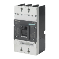
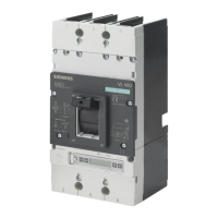
13.3 VL630 (3VL5), 3- and 4-pole, up to 630 A
3VL molded-case circuit breakers
System Manual, 03/2009, 110 0110 - 02 DS 01
229
13.3.3 Connections and phase barriers
Z
( 1 )
( 2 )
( 7 )
X
( 2 )
Y
( 1 )
( 8 )
( 1 )
X
7 6
2 7 0 . 5 ( 4 P )
9 7 . 5
4 2 6
9 . 5
2 2 4
2 9
1 0 6 . 5
4 0 9
6 3 . 5 ( 4 P )
6 3 . 5
2 1
6 3 . 5
4 2
1 5
2 0 0 . 5
3 7 9
2 5 . 5
1 9 4 . 5 ( 3 P )
9 7
2 1 5 . 5
4 0 9
2 0 0 . 5
X
Y
1 2 . 5
N S E 0 _ 0 1 1 8 4 b
1 2 . 5
3 7 9
Ø 1 1
( 3 )
( 7 )
X
Z
( 5 )
( 4 )
2 - 6
1 0 6 . 5
1 8
1 8
6 6 . 5
1 5
6 6 . 5
1 2 . 5
1 3 0 . 5
1 1 . 1
3 2
2 3 9 . 5
N S E 0 _ 0 1 1 8 5
(1) Interphase barrier
(2) Front connecting bars
(3) Terminal covers (standard)
(4) Rear connection (horizontal connection)
(5) Rear connection (vertical connection)
(7) Mounting level
(8) Flared busbar extensions

 Loading...


