Chapter 3
Communication Ports
RUGGEDCOM RS900G
Installation Guide
14 Copper Ethernet Ports
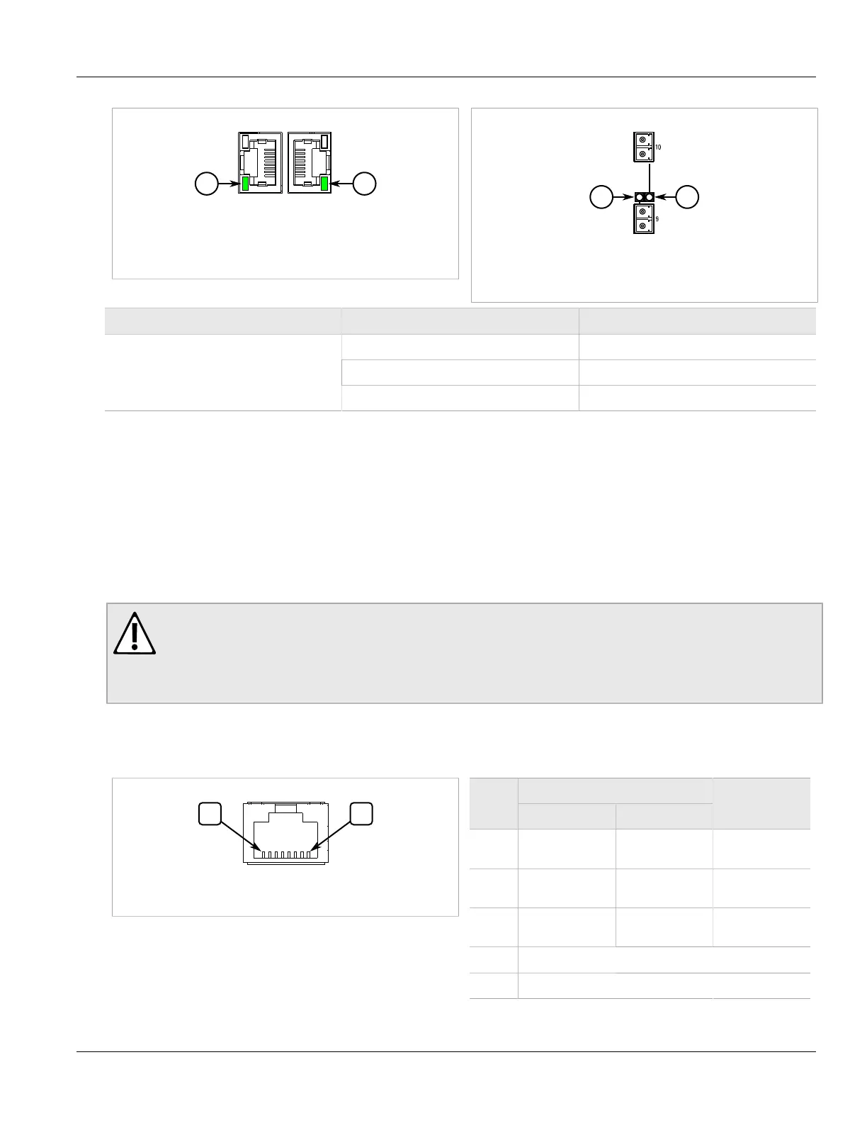
Figure 11: LED for Standard Copper RJ-45 Ports (1 to
8)
1. Link/Activity LED
Figure 12: LED for Optional Ports (9 to 10)
1. Link/Activity LED
LED State Description
Green (Solid) Link established
Green (Blinking) Link activity
Link/Activity
Off No link detected
Section 3.2
Copper Ethernet Ports
The RUGGEDCOM RS900G features eight 10/100Base-TX or 100/1000Base-TX copper RJ-45 Ethernet ports in
ports 1 to 8.
Each copper port is directly connected to chassis ground and accepts a standard Category 5 (CAT-5) Unshielded
Twisted-Pair (UTP) or Shielded Twisted-Pair (STP) cable.
WARNING!
Electric shock hazard – risk of serious personal injury and/or equipment interference. If shielded
cables are used, make sure the shielded cables do not form a ground loop via the shield wire and the
RJ-45 receptacles at either end. Ground loops can cause excessive noise and interference, but more
importantly, create a potential shock hazard that can result in serious injury.
Pin-Out
The following are the pin-out descriptions for the RJ-45 and micro-D connectors:
Figure 13: RJ-45 Port Pin Configuration
Name
Pin
10/100Base-TX 1000Base-TX
Description
1 RX+ BI_DB+ Receive Data+
or Bi-Directional
2 RX- BI_DB- Receive Data-
or Bi-Directional
3 TX+ BI_DA+ Transmit Data+
or Bi-Directional
4 Reserved (Do Not Connect)
5 Reserved (Do Not Connect)
 Loading...