Installing the Device
2.6.2Wiring Examples
c. Connect the ground wire to the
chassis/ground terminal on the
terminal block.
LO DC Power supply
a. Connect the Positive wire to
the positive (+) terminal on the
terminal block.
b. Connect the Negative wire to
the negative (-) terminal on the
terminal block.
c. Connect the ground wire to the
chassis/ground terminal on the
terminal block.
2
5 POS Terminal Block
3
Chassis/Ground Terminal
4
Negative Terminal
5
Positive Terminal
Figure2.9 Terminal Block Wiring
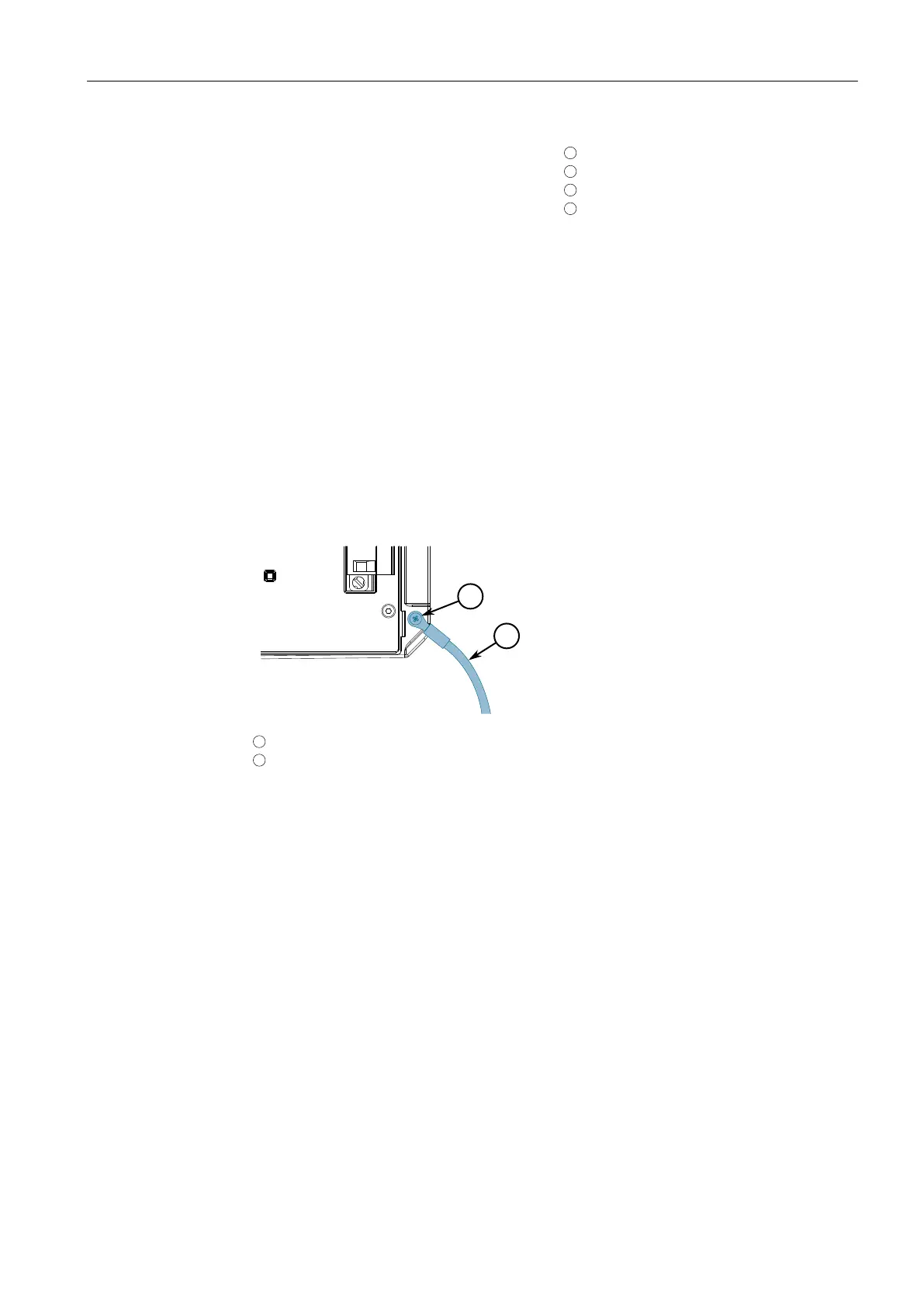
4. Connect the chassis ground screw to ground (Potential Earth). It is
recommended to terminate the ground connection with an M4 ring or spade
lug, and then torque to 1.7 N·m (15 lbf-in).
1
M4 Screw
2
M4 Ring Lug
Figure2.10 Chassis Ground Connection
5. Connect the external power supply to a power source. The Power LED on the
device will turn green when power is being supplied to the device.
2.6.2 Wiring Examples
The following illustrate how to connect single and dual power supplies to the device.
16
RUGGEDCOM RSG909R
Installation Manual, 02/2021, C79000-G8976-1388-12

 Loading...