Configuration, programming
4.4 IP configuration
CP 1543-1
38 Operating Instructions, 12/2019, C79000-G8976-C289-08
Figure 4-1 Principle of the virtual interface
Configuration of the virtual interface W1
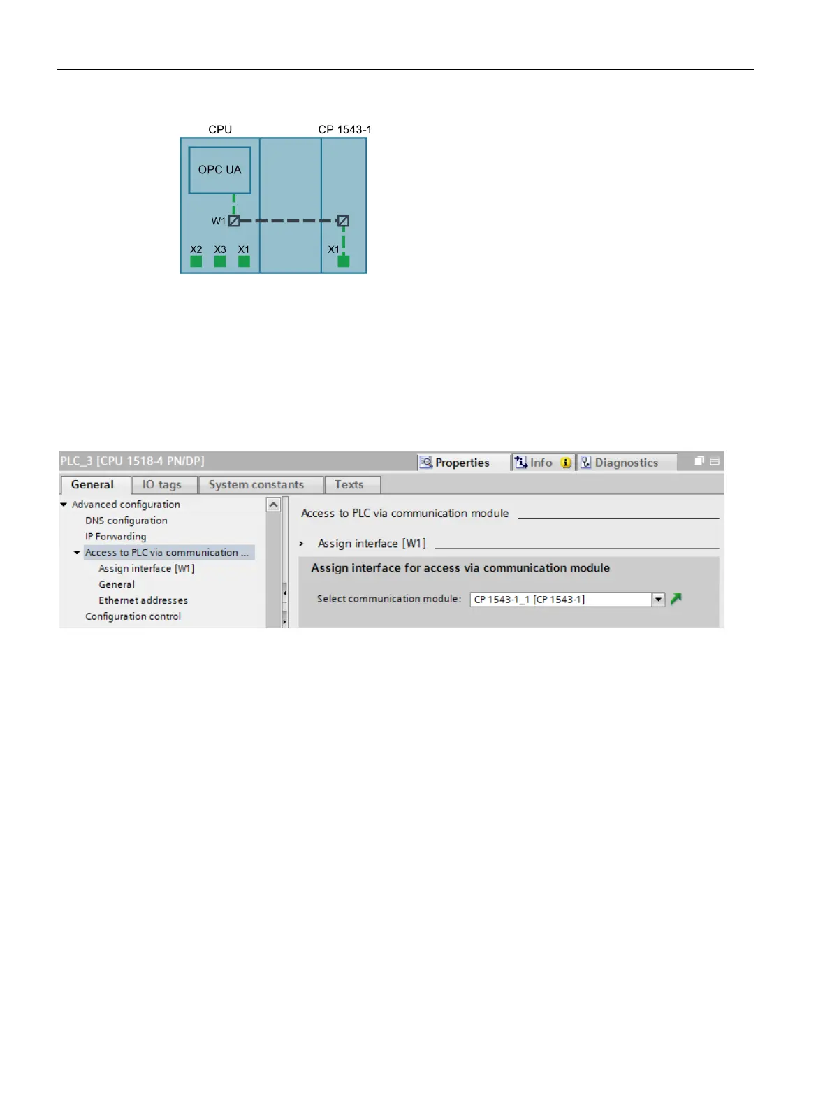
The virtual interface is configured in STEP 7 in the parameter group "Advanced configuration
> Access to PLC via communication module".
Here, the virtual interface is assigned to a CP of the station, via which external access to the
CPU can take place. The configured CPs of the station can be selected in the drop-down list.
Figure 4-2 Selecting the CP in the CPU properties
After selecting the CP, configure the IP and PROFINET parameters of the virtual interface.
Observe the following rules:
● The IP address of the virtual interface and the IP addresses of the PROFINET interfaces
of the CPU must be in different, disjointed address bands.
● The IP address of the virtual interface must be in the subnet of the Ethernet interface so
that the services of the CP can be reached from the CPU and vice versa.
After loading the configuration data, the CPU services such as the OPC UA server can be
reached via the CP and the virtual interface.
The IP address of the virtual interface is shown in the list of server addresses in the
properties dialog of the OPC UA server of the CPU. Created connections and S7
communication (e.g. HMI and BSEND, BRCV) run over this interface.
The IP address of the virtual interface W1 is not listed under the currently displayed local
interfaces (Xn) in the device display, but under "Addresses" in the "Settings" section. The
virtual interface is also visible when no CP is plugged or when the virtual interface is
deactivated. If there is no IP configuration, the IP address and subnet mask are shown with
0.0.0.0.

 Loading...