3 Installation and Commissioning
B−14
CP 343-1 Lean for Industrial Ethernet / Manual Part B
Release 09/2009
C79000-G8976-C198-06
Step Explanation / meaning
6. Use the diagnostic functions during
commissioning and to analyze problems.
The following options are available:
S The LED displays on the CP
S Hardware diagnostics and troubleshooting with
STEP 7
S Communication diagnostics with STEP 7 / NCM
Diagnostics
S Standard information using HW Config
S Web diagnostics
S If applicable, evaluation of the alarm block
FB54 in the user program
S Queries via SNMP
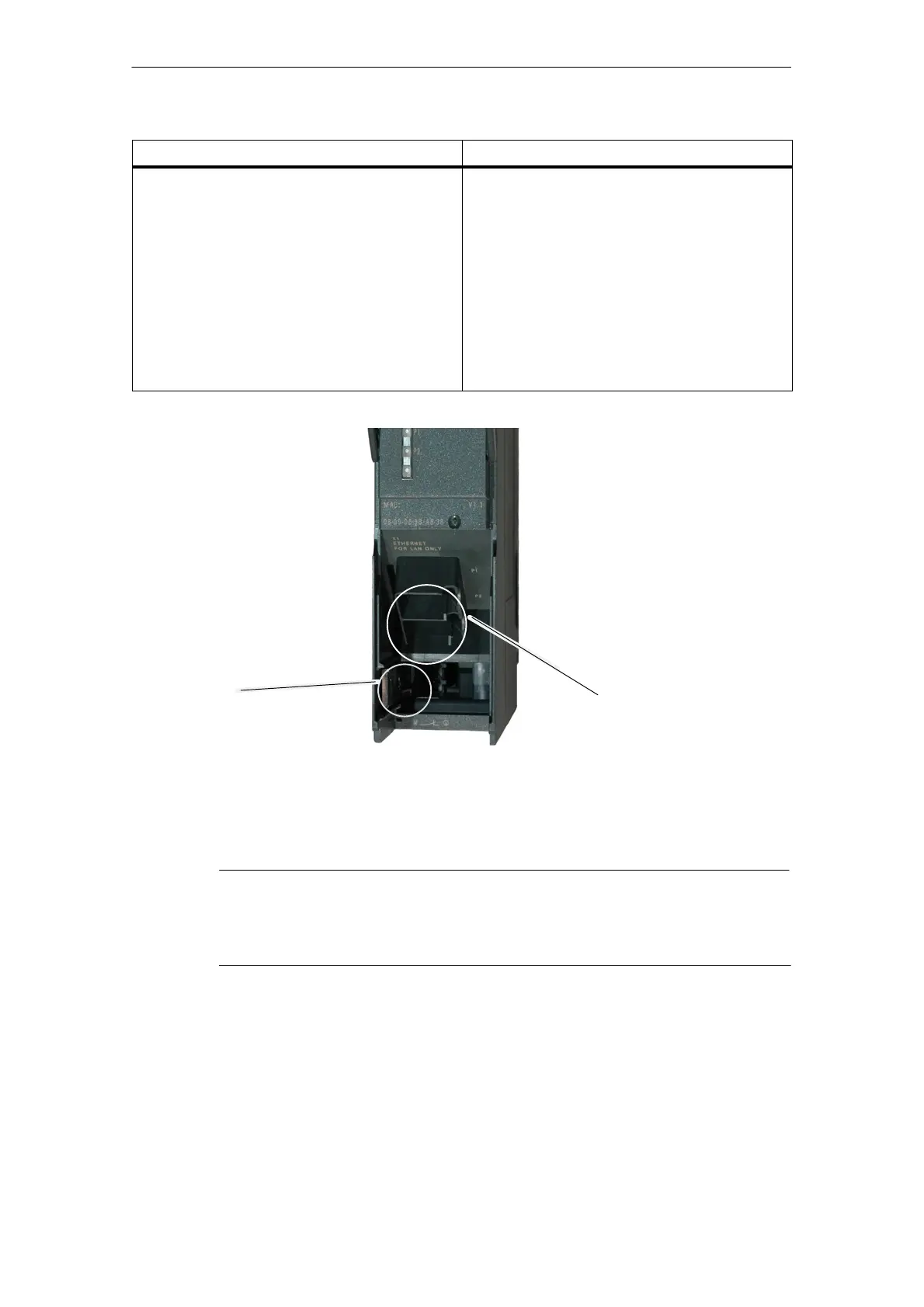
Slider for setting the
chassis ground contact
Attachment to Industrial Ethernet:
2 x 8-pin RJ-45 jack
Figure 3-1 Connectors of a CP 343−1 Lean with the front panel open
Ground/chassis ground concept
Notice
Please note the instructions regarding the grounding and chassis ground concept
in the SIMATIC S7 installation guides; see “SIMATIC S7 Programmable Controller
S7−300 − Installation and Hardware: Installation Manual” /1/.
Behind the hinged panel on the left of the device, you will see a slider with which
you can connect or disconnect the chassis ground of the 24 V power supply with
reference ground.
S Slider pushed in: chassis and reference ground connected (note: the slider
must be felt to lock in place).