3-2
PP7,
PP17-I, PP17-II Equipment Manual
Release 06/98
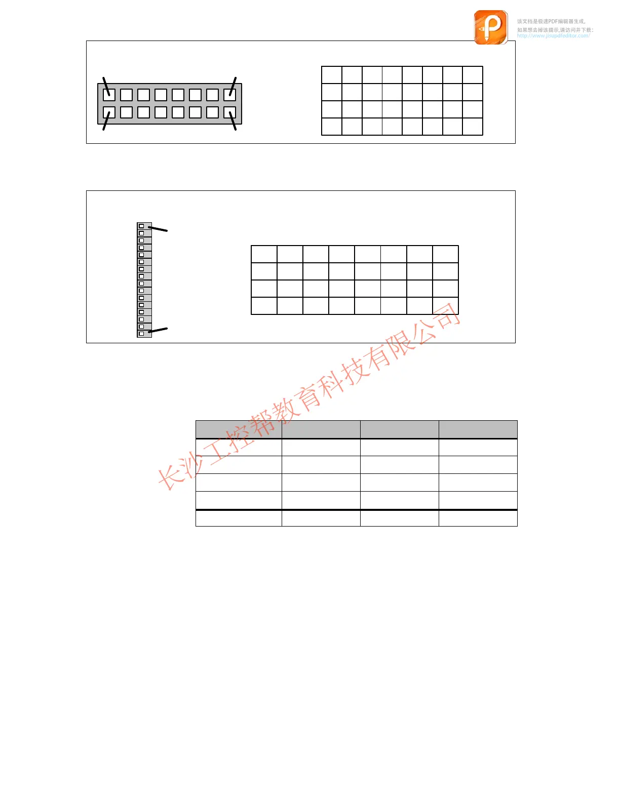
LEDs
8
1
16
9
Bit 7 Bit 0
L8 L1
L8 L1
L16 L9
L16 L9
Byte n
Byte n+1
Byte n+2
Byte n+4
Red
Green
Red
Green
Figure 3-3 Numeration of the LEDs on the Push Button Panel
1
16
Digital outputs
Bit 7 Bit 0
Byte n
Byte n+1
Byte n+2
Byte n+4
DO8 DO1
DO8 DO1
DO16 DO9
DO16 DO9
Figure 3-4 Numeration of the digital outputs on the Push Button Panel
The
following table indicates the data area for keys, LEDs, digital inputs and
digital outputs of the Push Button Panel in the PLC:
Marker ar
ea PP7 PP17-I PP17-II
Keys
1 Byte
2 Bytes 4 Bytes
Digital inputs
1 Byte
2 Bytes 2 Bytes
LEDs
2 bytes
4 Bytes 8 Bytes
Digital outputs
-
4 Bytes 4 Bytes
Total
4 Bytes
12 Bytes 18 Bytes
A data area for the entire length must be set up, even when the full functional
capacity of the unit is not used.
该文档是极速PDF编辑器生成,
如果想去掉该提示,请访问并下载:
http://www.jisupdfeditor.com/