25
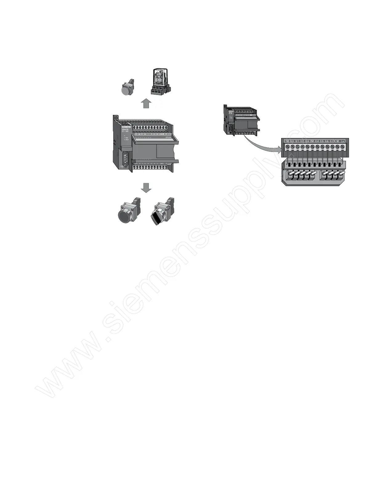
Inputs and Outputs Input devices, such as switches, pushbuttons, and other
sensors are connected to the terminal strip under the bottom
cover of the PLC.
Local Input Points
Local Output Points
SF/DIAG
Output Devices
Input Devices
SF/DIAG
Input Simulator
A convenient method of testing a program is to wire toggle
switches to the inputs. Input simulators with pre-wired toggle
switches are available for use with S7-200 PLCs. Switches are
wired between the 24 VDC power supply (L+) and the inputs.
For example, the switch on the far left is wired between the
first input (0.0) and L+. When the switch is closed, 24 VDC is
applied to the input. When the switch is open, 0 VDC is applied
to the input.
Output devices, such as relays, are connected to the terminal
strip under the top cover of the PLC. When testing a program,
it is not necessary to connect output devices. The LED status
indicators signal if an output is active.
 Loading...


