29
I/O Numbering S7-200 inputs and outputs are labeled at the wiring terminations
and next to the status indicators. These alphanumeric symbols
identify the I/O address to which a device is connected. This
address is used by the CPU to determine which input is present
and which output needs to be turned on or off.
I designates a discrete input and Q designates a discrete
output. The first number identifies the byte, the second number
identifies the bit.
Image register space for digital I/O is always reserved in
increments of eight bits (one byte). If a module does not
provide a physical point for each bit of each reserved byte,
these unused bits cannot be assigned to subsequent modules
in the I/O chain.
Each analog I/O point is associated with a 16-bit word in the
S7-200 PLC and is identified by AI (for analog input) or AQ
(for analog output) followed by a W (representing a word of
memory) and a starting byte number. Analog I/O words start on
even-numbered bytes (such as 0, 2, or 4).
Analog I/O points are always allocated in increments of two
points. If a module does not provide physical I/O for each of
these points, these I/O points are lost and are not available for
assignment to subsequent modules in the I/O chain.
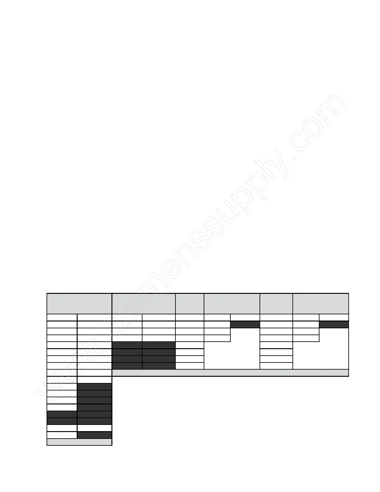
The following example shows the addressing for one sample
application.
Module 1 Module 3
14 D isc re te In 10 D isc re te O u t
2 A na log In 1 A na log O ut 4 D isc re te In 4 D iscrete O ut 8 D is crete In 4 A na log In 1 A na log O ut 8 D isc re te O ut 4 A na log In 1 A nalog O ut
I0.0 Q 0.0 I2.0 Q 2.0 I3.0 AIW 4 A QW 4 Q 3.0 A IW 12 AQ W 8
I0.1 Q 0.1 I2.1 Q 2.1 I3.1 AIW 6 A QW 6 Q 3.1 A IW 14 A Q W 10
I0.2 Q 0.2 I2.2 Q 2.2 I3.2 AIW 8 Q 3.2 A IW 16
I0.3 Q 0.3 I2.3 Q 2.3 I3.3 A IW 10 Q 3.3 A IW 18
I0.4 Q 0.4 I2.4 Q 2.4 I3.4 Q 3.4
I0.5 Q 0.5 I2.5 Q 2.5 I3.5 Q 3.5
I0.6 Q 0.6 I2.6 Q 2.6 I3.6 Q 3.6
I0.7 Q 0.7 I2.7 Q 2.7 I3.7 Q 3.7
I1.0 Q 1.0 Expa ns ion I/O
I1.1 Q 1.1
A ddress es show n with a blac k b ack g ro und are n ot availab le an d c ann ot be us ed in the pro gra m .
I1.2 Q 1.2
I1.3 Q 1.3
I1.4 Q 1.4
I1.5 Q 1.5
I1.6 Q 1.6
I1.7 Q 1.7
A IW 0 A Q W 0
A IW 2 A Q W 2
Loc al I/O
 Loading...


