34
STEP 7-Micro/WIN has three editors for program development,
one for each of the types of programming available, ladder logic
(LAD), statement list (STL), and function block diagram (FBD).
The STL editor is often preferred by experienced programmers
because of the similarity of STL programs to assembly
language computer programs. However, the STL editor can only
be used with the SIMATIC instruction set. Both the LAD and
FBD editors can be used with either instruction set. Throughout
this course, although other instruction types will occasionally be
shown, the emphasis will be on SIMATIC LAD instructions.
Basic Ladder Logic Symbols PLC ladder logic consists of a commonly used set of symbols
that represent instructions. Understanding these basic symbols
is essential to understanding PLC operation.
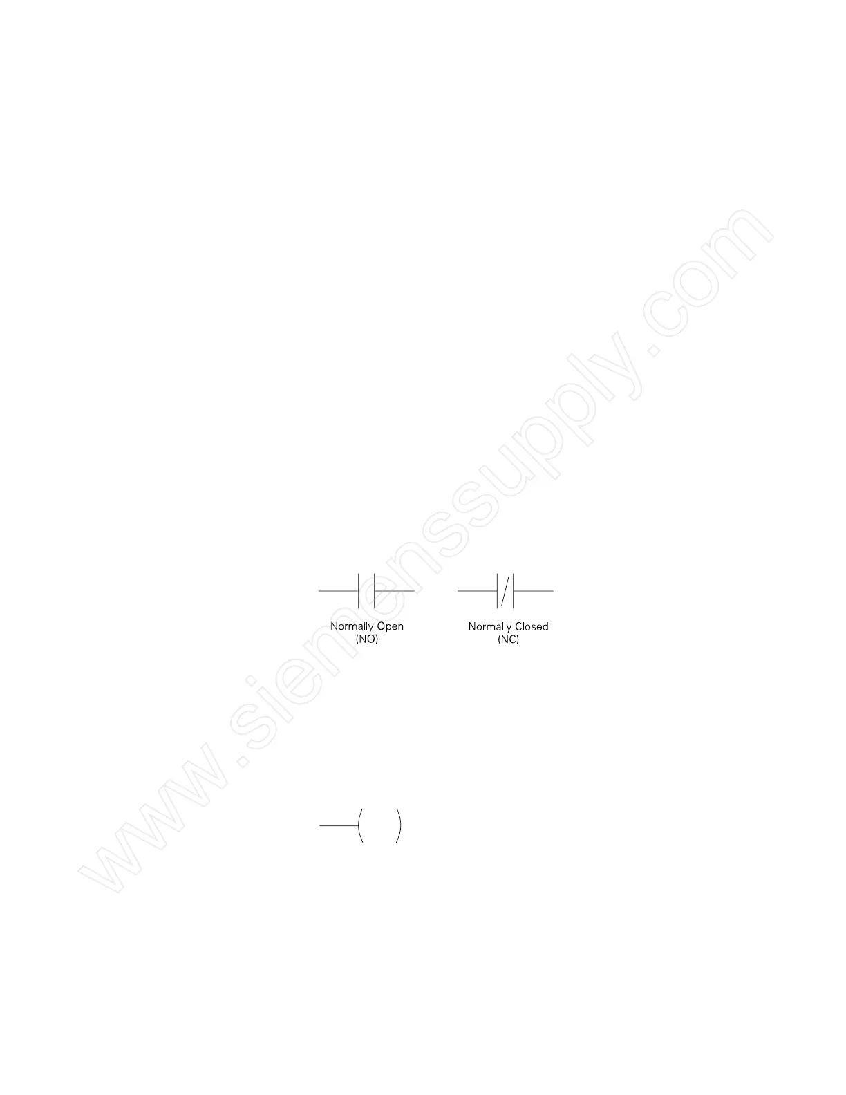
Contacts One of the most confusing aspects of PLC programming for
first-time users is the relationship between the device that
controls a status bit and the programming function that uses
a status bit. Two of the most common programming functions
are the
normally open (NO) contact and the normally
closed (NC) contact. Symbolically, power flows through these
contacts when they are closed. The normally open contact (NO)
is closed when the input or output status bit controlling the
contact is 1. The normally closed contact (NC) is closed when
the input or output status bit controlling the contact is 0.
Coils Coils represent relays that are energized when power flows
to them. When a coil is energized, it causes a corresponding
output to turn on by changing the state of the status bit
controlling that output to 1. That same output status bit may be
used to control normally open and normally closed contacts
elsewhere in the program.
 Loading...


