EasyManuals Logo

Siemens Simatic S7 Series User Manual

Siemens Simatic S7 Series
75 pages
To Next Page IconTo Next Page
To Previous Page IconTo Previous Page
Page #36 background imageLoading...
Page #36 background image
35
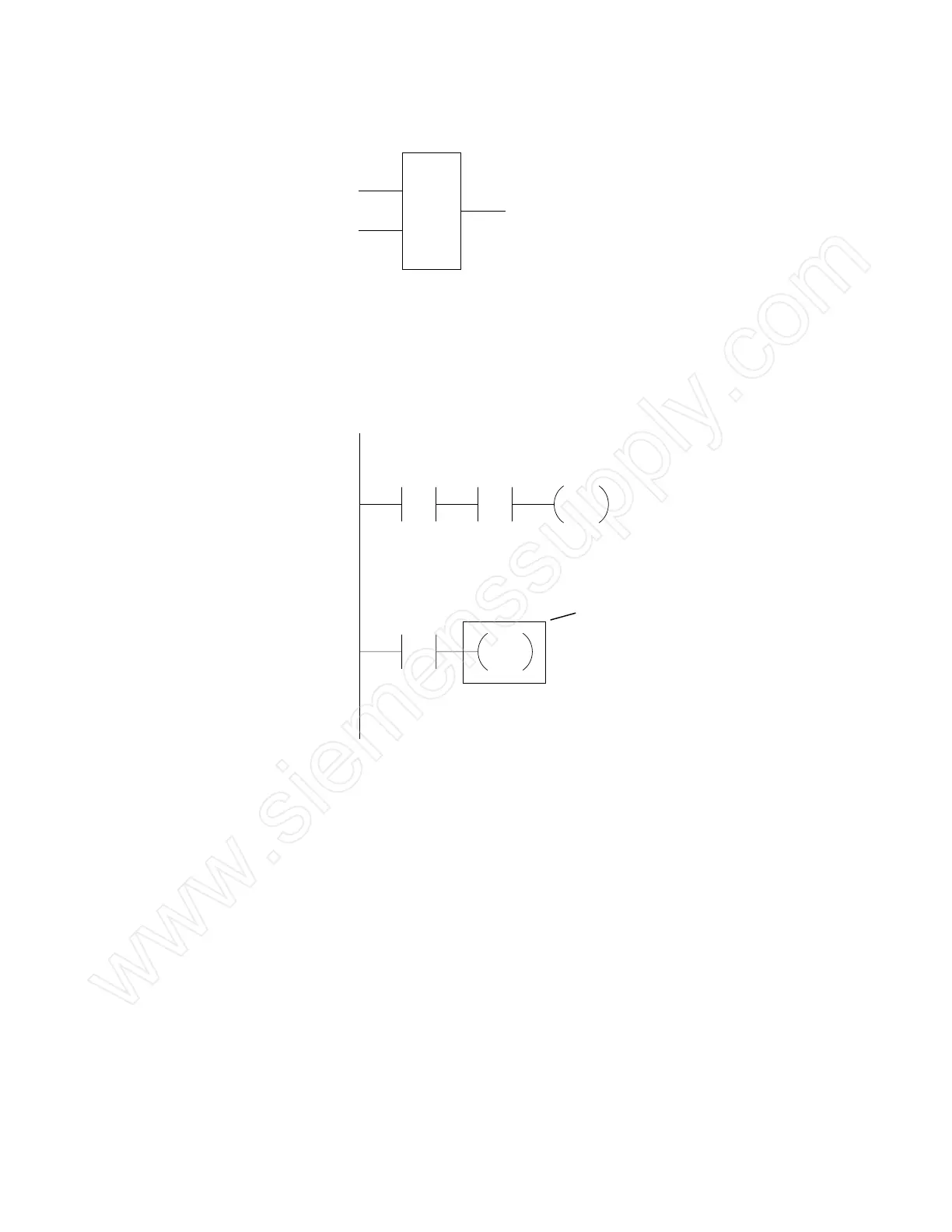
Boxes Boxes represent various instructions or functions that are
executed when power flows to the box. Typical box functions
include timers, counters, and math operations.
Entering Elements Control elements are entered in the ladder diagram by
positioning the cursor and selecting the element from a list.
In the following example the cursor has been placed in the
position to the right of I0.2. A coil was selected from a pull-
down list and inserted in this position.
Network 1
Network 2
I0.0 I0.1
I0.2
Q0.0
Cursor
www.siemenssupply.com

Other manuals for Siemens Simatic S7 Series

Questions and Answers:

Question and Answer IconNeed help?

Do you have a question about the Siemens Simatic S7 Series and is the answer not in the manual?

Siemens Simatic S7 Series Specifications

General IconGeneral
CPUVaries by model (e.g., S7-300, S7-400, S7-1200, S7-1500)
Communication InterfacesPROFIBUS, PROFINET, Ethernet, MPI
ProgrammingTIA Portal, STEP 7
Programming LanguagesLAD, FBD, STL, SCL, GRAPH
I/O ModulesDigital, Analog, Specialty modules available
Operating Temperature0°C to 60°C (standard models)
MountingDIN rail mounting
Operating Voltage24V DC or 120/230V AC (varies by model)
Protection ClassIP20 (standard models)
MemoryVaries depending on the S7 model. Includes work memory (RAM) for program execution, load memory (EEPROM or Flash) for program storage, and system memory for operating system functions. Memory sizes range from kilobytes to megabytes.

Related product manuals