EasyManuals Logo

Siemens Simatic S7 Series User Manual

Siemens Simatic S7 Series
75 pages
To Next Page IconTo Next Page
To Previous Page IconTo Previous Page
Page #37 background imageLoading...
Page #37 background image
36
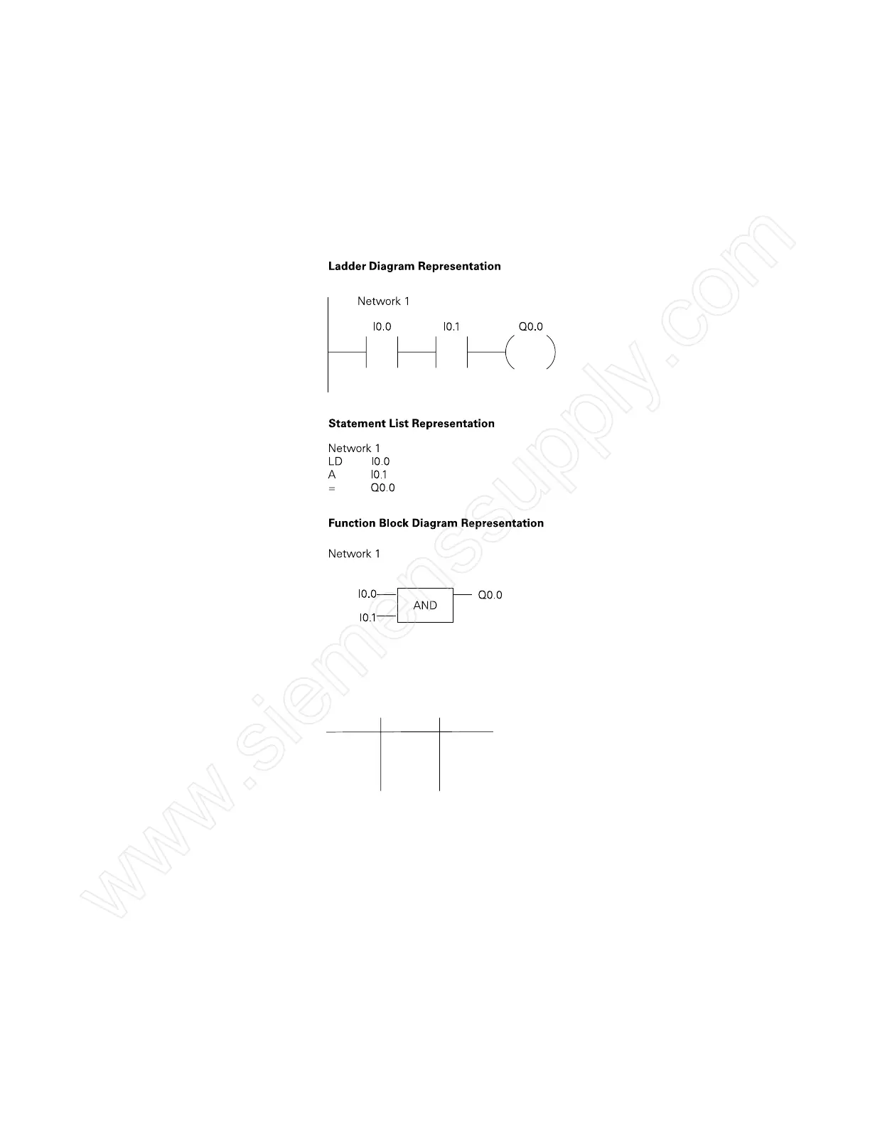
AND Operation Each rung or network on a ladder represents a logic operation.
The following programming example demonstrates an
AND
operation. Two contact closures and one output coil are placed
on network 1. They are assigned addresses I0.0, I0.1, and Q0.0.
Note that in the statement list a new logic operation always
begins with a load instruction (LD). In this example I0.0 (input 1)
and (A in the statement list) I0.1 (input 2) must be true in order
for output Q0.0 (output 1) to be true. This same logic is also
shown in a function block diagram.
The following truth table represents the state of the output for
each combination of input states.
I0.0 I0.1
Q0.0
0
0
1
1
0
1
0
1
0
0
0
1
www.siemenssupply.com

Other manuals for Siemens Simatic S7 Series

Questions and Answers:

Question and Answer IconNeed help?

Do you have a question about the Siemens Simatic S7 Series and is the answer not in the manual?

Siemens Simatic S7 Series Specifications

General IconGeneral
CPUVaries by model (e.g., S7-300, S7-400, S7-1200, S7-1500)
Communication InterfacesPROFIBUS, PROFINET, Ethernet, MPI
ProgrammingTIA Portal, STEP 7
Programming LanguagesLAD, FBD, STL, SCL, GRAPH
I/O ModulesDigital, Analog, Specialty modules available
Operating Temperature0°C to 60°C (standard models)
MountingDIN rail mounting
Operating Voltage24V DC or 120/230V AC (varies by model)
Protection ClassIP20 (standard models)
MemoryVaries depending on the S7 model. Includes work memory (RAM) for program execution, load memory (EEPROM or Flash) for program storage, and system memory for operating system functions. Memory sizes range from kilobytes to megabytes.

Related product manuals