42
The motor will run until the normally closed Stop button
is pressed, unless the overload relay (OL) contacts open.
When the Stop button is pressed, the path for current flow is
interrupted, opening the associated M and Ma contacts, and
the motor stops.
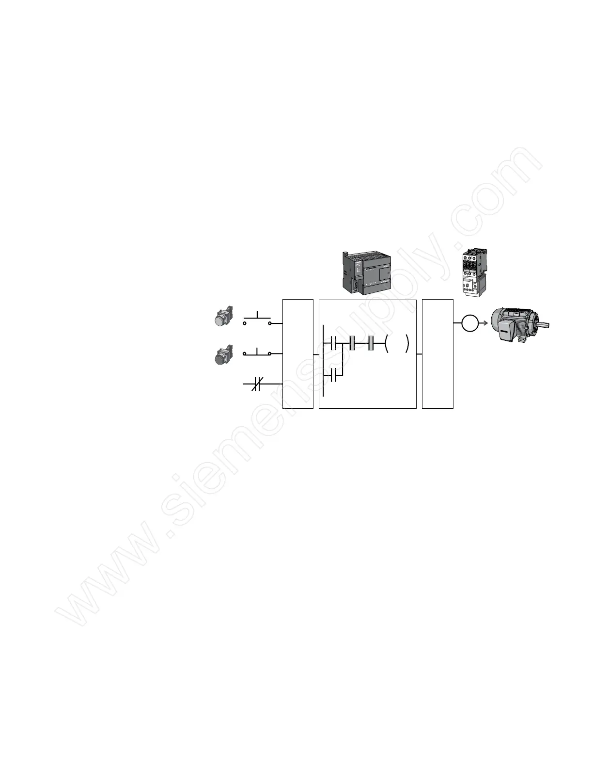
PLC Motor Control This motor control application can also be accomplished
with a PLC. In the following example, a normally open Start
pushbutton is wired to the first input (I0.0), a normally closed
Stop pushbutton is wired to the second input (I0.1), and
normally closed overload relay contacts (part of the motor
starter) are connected to the third input (I0.2). These inputs are
used to control normally open contacts in a line of ladder logic
programmed into the PLC.
SF/DIAG
Start (NO)
Stop (NC)
OL
I0.0
I0.1
I0.2
Input
Points
Output
Point
Q0.0
Network 1
CPU Program
I0.0 I0.1 I0.2
Q0.0
Q0.0
Motor
Starter
Motor
Initially, I0.1 status bit is a logic 1 because the normally closed
(NC) Stop Pushbutton is closed. I0.2 status bit is a logic 1
because the normally closed (NC) overload relay (OL) contacts
are closed. I0.0 status bit is a logic 0, however, because the
normally open Start pushbutton has not been pressed.
Normally open output Q0.0 contact is also programmed on
Network 1 as a sealing contact. With this simple network,
energizing output coil Q0.0 is required to turn on the motor.
 Loading...


