44
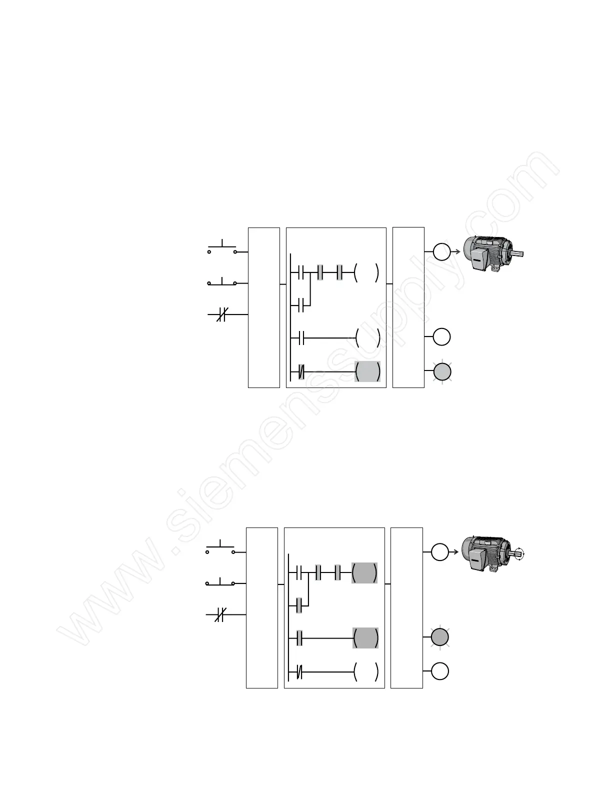
Adding Run and Stop The application can be easily expanded to include indicator
Indicator Lights lights for run and stop conditions. In this example, a RUN
indicator light is connected to output Q0.1 and a STOP indicator
light is connected to output Q0.2.
The ladder logic for this application includes normally open
Q0.0 contact connected on Network 2 to output coil Q0.1
and normally closed Q0.0 contact connected on Network 3
to output coil Q0.2. When Q0.0 is off, the normally open Q0.0
contact on Network 2 is open and the RUN indicator off. At the
same time, the normally closed Q0.0 contact is closed and the
STOP indicator is on.
Start (NO)
Stop (NC)
OL
I0.0
I0.1
I0.2
Input
Points
Output
Points
Q0.0
Network 1
CPU Program
I0.0 I0.1 I0.2
Q0.0
Q0.0
Motor
Starter
Motor
Q0.1
Q0.2
Q0.1
Q0.2
Q0.0
Q0.0
Network 2
Network 3
STOP Indicator
RUN Indicator
Motor is
Stopped
When the Start button is pressed, the PLC starts the motor.
Output Q0.0 is now on. Normally open Q0.0 contact on
Network 2 is now closed and the RUN indicator is on. At the
same time, the normally closed Q0.0 contact on Network 3 is
open and the STOP indicator light connected to output Q0.2 is
off.
Motor is
Running
Start (NO)
Stop (NC)
OL
I0.0
I0.1
I0.2
Input
Points
Output
Points
Q0.0
Network 1
CPU Program
I0.0 I0.1 I0.2
Q0.0
Q0.0
Motor
Starter
Motor
Q0.1
Q0.2
Q0.1
Q0.2
Q0.0
Q0.0
Network 2
Network 3
STOP Indicator
RUN Indicator
 Loading...


