s
© Siemens AG 2013-2015 A5E43029185
To ensure better heat dissipation, do not insert any insulators between
the motor flange and the mounting flange.
Mount the motor through a mounting steel
flange, as shown in the left figure.
• Low inertia motor:
2 x M4 (1FL602❑)
❑
)
Tightening torque 4.7 Nm
❑
4 x M8 (1FL605❑)
120x100x40
• High inertia motor:
❑
)
Tightening torque: 8 Nm
❑
)
Tightening torque: 20 Nm
4 x M12 (1FL609❑)
420x420x20
Use a flexible coupling with high torsional
rigidity specifically designed for servo
motors, which allow to transfer the motor
torque to the mechanics and to
compensate radial, axial and angular
misalignments.
Do not strike the shaft when installing a
coupling and ensure that the radial and
axial forces are smaller than the allowable
maximum values specified in the Operating
When a motor is used with a flange coupling, ensure that the radial
deviation is smaller than 0.03 mm. Otherwise, the bearing will be
The required alignment accuracy differs with the motor speed and the
coupling type. Please determine the accuracy according to actual
• Turn the motor shaft and the machine
shaft to align the coupling.
• An alignment accuracy test is preferred.
If unachievable, judge the accuracy by
observing whether the coupling can slide
smoothly on both shafts.
If the coupling gives out abnormal sounds, refer to the step “Aligning a
coupling” to realign the coupling until the sounds disappear.
The belt tension must be smaller than the allowable radial forces of the
• Measure the belt tension at multiple
points using a tension meter while
turning the motor shaft by 45°.
• Try your best to reduce the axial
misalignment of the belt-pulleys to keep
the axial forces to the motor shaft to a
minimum
.
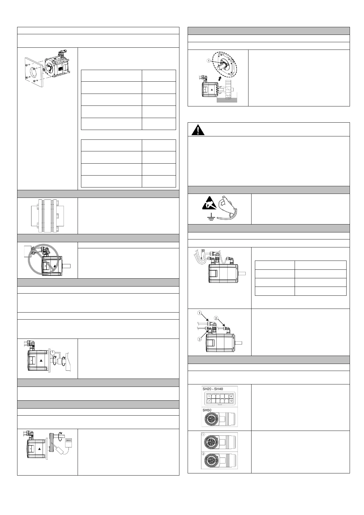
Do not use a motor with an oil seal submerged in oil.
The oil seal (①) should be used with
sufficient lubricant oil splashed on it.
4 Electrical installation
Personal injuries by hazardous voltage and unregulated move
If you connect the cables with the power supply switched on, it may
cause personal injuries by a hazardous voltage and unregulated move
from the motor.
• Switch off the power supply.
• Make sure that there are no voltage conditions.
• Prevent the energy sources from switching on again.
Before connecting the cables, you must
take necessary ESD protection measures,
e.g. wearing an ESD wrist strap, ESD
gloves, and ESD clothes.
Do not put much stress upon cables or connectors while wiring.
The minimum cable bending radiuses
are listed as follows:
Type Radius
Power cable 6 x outer diameter
Encoder cable 6 x outer diameter
Brake cable 6 x outer diameter
The minimum dynamic bending radius
Connect the cables in the following order:
1. Encoder cable (③)
2. Brake cable (②)
3. Power cable (①)
Connecting the encoder cable
Do not touch the encoder pins at the motor with naked hands to avoid
For the low inertia motor with shaft-height
50 mm, the incremental encoder cable
connector has two notches.
For the high inertia motor, the absolute
encoder cable connector (①) has three
notches. The incremental encoder cable
connector (②) has two notches.