s
© Siemens AG 2013-2015 A5E43029185
4. Electrical, magnetic and electromagnetic fields generated in
operation that can pose a risk to people with a pacemaker,
implants or metal replacement joints, etc., if they are too close.
5. Release of environmental pollutants or emissions as a result of
improper operation of the system and/or failure to dispose of
components safely and correctly.
The components must be protected against conductive contamination
(e.g. by installing them in a control cabinet with degree of protection
IP54 according to IEC 60529 or NEMA 12).
Assuming that conductive contamination at the installation site can
definitely be excluded, a lower degree of cabinet protection may be
permitted.
For more information about residual risks of the components in a drive
system, see the relevant sections in the technical user documentation.
1.5 Warning labels
Warning labels on servo motors
Do not strike the shaft end or the keyway.
The surface temperature of the motor may exceed 80°C. Do
not touch the hot surfaces.
Warning labels in this document
Indicates that death, severe personal injuries or material
damages may result if proper precautions are not taken.
Indicates the actions that must not be performed.
2 Installation environment
• Operation:
− Low inertia motor: 0°C to 40°C
− High inertia motor: 0°C to 40°C
Note: When the surrounding
temperature is between 30 °C and
40 °C, the 1FL605❑ motors and
1FL609❑ motors with brake will have a
power derating of 10%.
• Storage:
− Low inertia motor: -20°C to 65°C
− High inertia motor: -15°C to 65°C
• Operation: ≤ 90% RH (non-condensing
at 30°C)
• Storage: ≤ 90% RH (non-condensing at
30°C)
≤ 1000 m
≤ 49 m/s
2
• Continuous axial shock:
≤ 25 m/s
2
• Continuous radial shock: ≤ 50 m/s
2
• Short-term (6 ms) shock:
≤ 250 m/s
2
To avoid magnetic interference to the absolute encoder, do not use
electromagnetic devices near the absolute encoder, such as
electromagnetic memory sticks, memory cards, and key cards.
Keep the servo motor with an absolute
encoder at least 15 mm away from the
devices that produce a magnetic field
stronger than 10 mT.
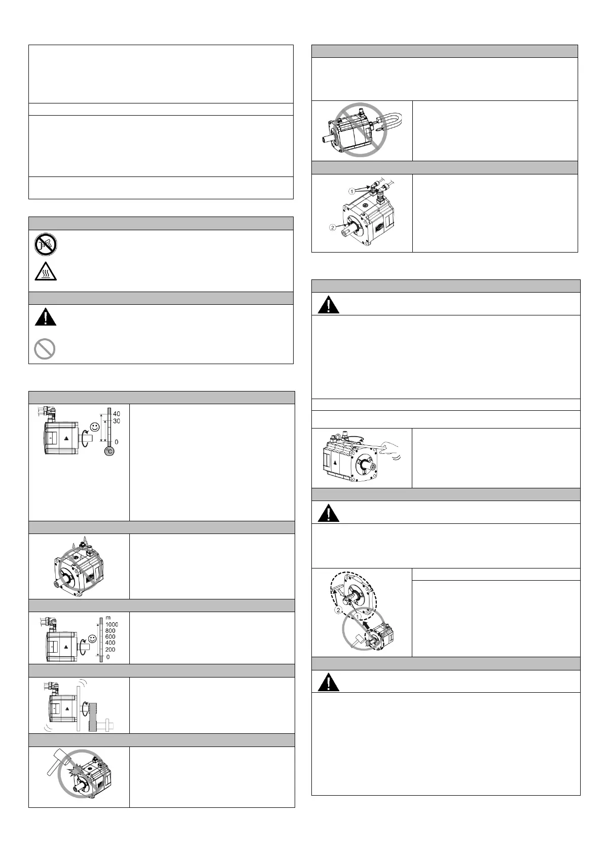
• A motor with fitted connectors has a
protection class of IP65 (dust-tight and
water jetting proof). The shaft opening
(②) is protected with an oil seal.
• To guarantee adequate protection, use
specified connectors
(①) when wiring.
3 Mechanical installation
Lifting a motor (for high inertia motor only)
Death or injuries by unresolved burdens
At the transport the motor can cause death or injuries by unchecked
movements.
• Use lifting equipments and load suspension devices which are only
interpreted for the burden of the motor and intact.
• Do not stay under and in the jib range of unresolved burdens.
• Safeguard the motor against rolling away at the side when removing.
• Do not lift a motor by pulling the cables.
Do not overtighten the eyebolts of 1FL609❑ motors.
• For 1FL609❑ motors, the eyebolts must
be manually screwed in completely.
• Lift 1FL609❑ motors at the eyebolts.
Installing a key (optional)
Injuries by an ejected key
When a motor using a key is running, the fitted key on the shaft may be
ejected, which can cause personal injuries. The fitted key on the shaft
must be firmly secured to prevent them from being flung out.
For the motor using a key (②), the key is
preinstalled on the shaft extension. When
reinstalling it, do not strike the key slot (①).
Personal injuries and material damages by the drop of a vertical
axis
When a servo motor with a brake is used as a vertical axis, the axis will
drop if the positive and negative poles of the 24 V DC power supply for
the servo drive are connected inversely. Unexpected drop may cause
personal injuries and material damages.
Before commissioning, mechanical end stops should be fixed at the
end of the absolute traversing range of the machine axis in prevention
of an unexpected drop. In addition, make sure that the 24 V DC power
supply is correctly connected.