Digital I/Os (parameterizable)
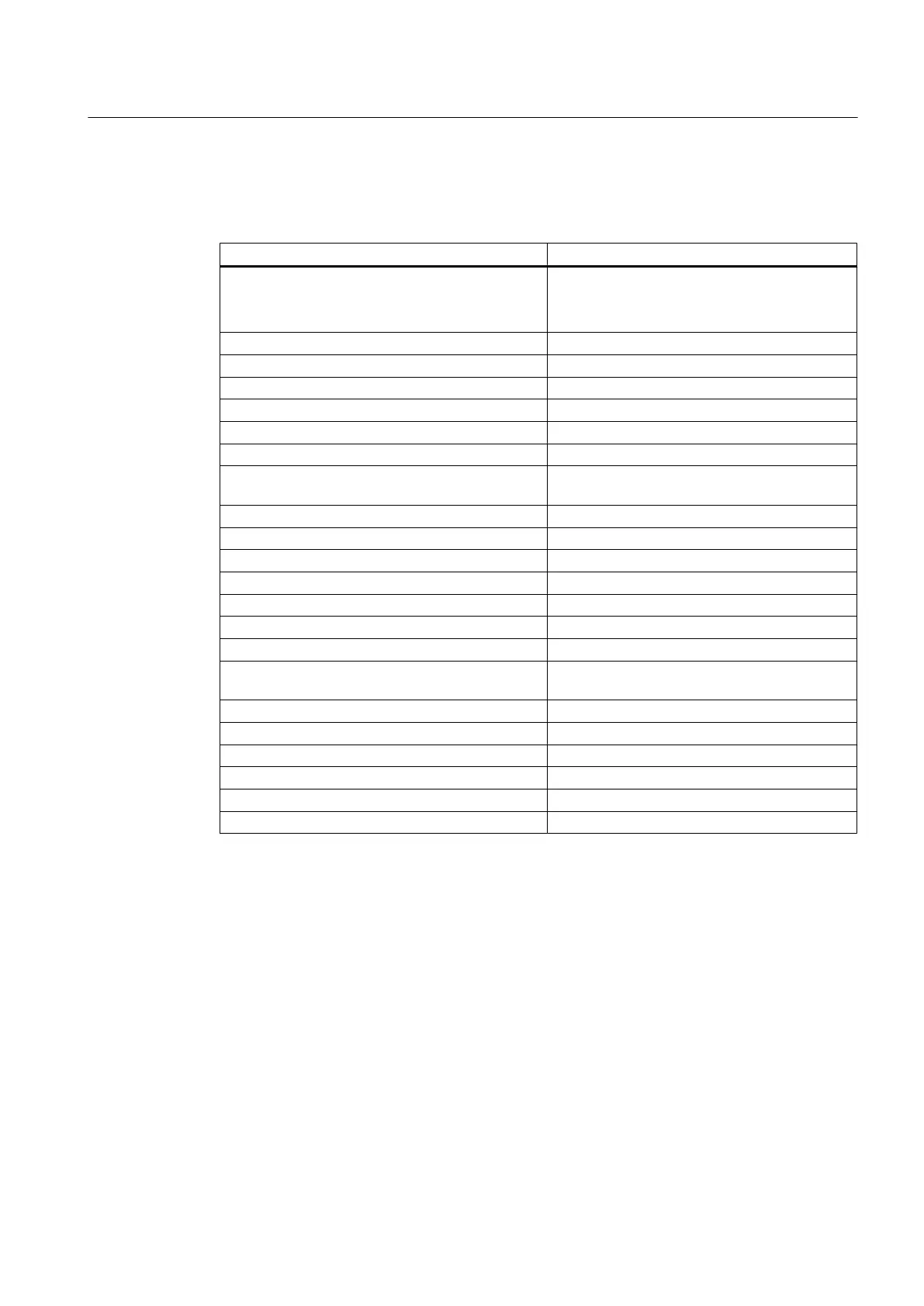
Table 7-35
Digital inputs/outputs on SIMOTION CX32‑2
Data SIMOTION CX32‑2
Number of digital inputs/outputs 4
●
Max. 4 as measuring input inputs
● Max. 0 as output cam outputs
If used as an input:
● Input voltage, rated value 24 V DC
● Input voltage, for signal "1" 15 … 30 V
● Input voltage, for signal "0"
2)
-3 … +5 V
Galvanic isolation no
Current consumption typ. at signal level "1" 9 mA at 24 V
Input delay, typical (hardware) Signal "0" → "1": 5 µs
Signal "1" → "0": 50 µs
Measuring input input, resolution 1 µs
Measuring input input, reproducibility 5 µs
If used as an output
● Rated load voltage, permissible range 24 V DC, 20.4 to 28.8 V
● Galvanic isolation no
● Current load, max. 500 mA per output
● Residual current, max. 2 mA
● Output delay, typ./max. (hardware)
1)
Signal "0" → "1": 150 µs/400 µs
Signal "1" → "0": 75 µs / 100 µs
Switching frequency of the outputs, max.
● With resistive load 4 kHz
● With inductive load 2 Hz
● With lamp load 11 Hz
Maximum lamp load 5 W
Short-circuit protection yes
1)
Data for: Vcc = 24 V; load 48 Ohm; H = 90% V
out
, L = 10% V
out
2)
The digital inputs are protected against polarity reversal up to -30 V
Max. switching frequency of the DO
The
max. switching frequency of the hardware depends on the load. For an ohmic load of 24 V/
0.5 A, it is up to 4 kHz. (typical value; low-high ratio = 50:50; short cable lengths).
Logic control of the digital output is also a limiting factor.
If an X122/X132 DO is set or reset from the user program, no more than 1 edge is possible
per servo or CU sampling time of the inputs/outputs (cu.p0799[0]).
With servo cycles of at least 500 µs, a max. switching frequency of 1 kHz is achieved.
The max. achievable switching frequency can also be limited by the CU parameter p0799[0]
(sampling time of the inputs/outputs of the CU) or p2048 (PROFIdrive PZD sampling time).
Supplementary system components
7.5 CX32-2 controller extension
SIMOTION D4x5-2
Manual, 04/2014 129