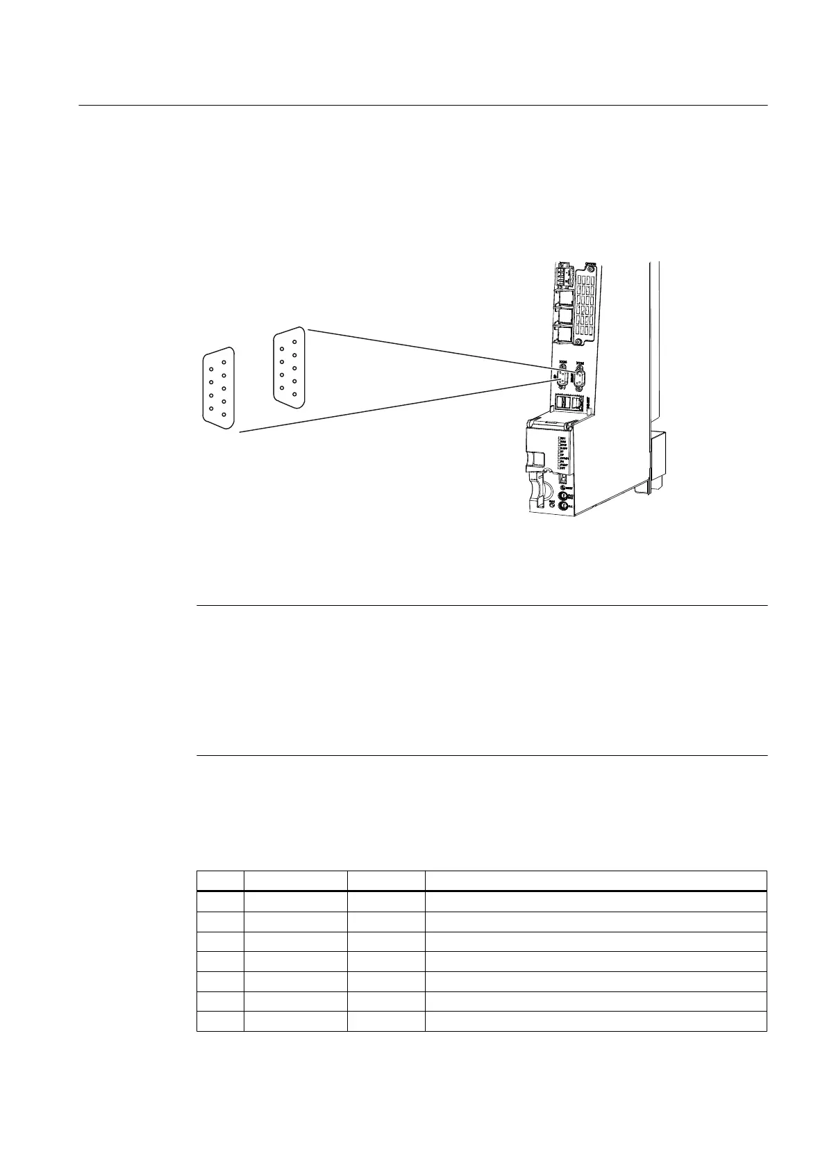
Position of connectors
The following figure shows the mounting position and designation of the connectors on the
control unit.
Figure 4-8 The position of the PROFIBUS X126 and X136 interfaces (example of SIMOTION D4x5‑2
DP/PN)
Note
For
the X126 interface, an adapter connector is available for raising the PROFIBUS connector
to make more cabling space. This connector is required in certain wiring scenarios.
For further details, see
● Section Available spare parts and accessories (Page 135)
●
SIMOTION D4x5‑2
Commissioning and Hardware Installation Manual, Section
Connecting PROFIBUS DP
Interface assignment for X126
Table 4-17
PROFIBUS DP interface X126
Pin Signal name Signal type Meaning
1 -- -- Reserved, do not use
2 M VO Ground to P24_SERV
3 1RS_DP B RS-485 differential signal
4 1RTS_DP O Request to send
5 1M VO Ground to 1P5
6 1P5 VO 5 V power supply for bus terminal, external, short-circuit proof
7 P24_SERV VO 24 V for teleservice, short-circuit proof, 150 mA maximum
Interfaces
4.7 PROFIBUS DP interfaces
SIMOTION D4x5-2
Manual, 04/2014 71