VII
Siemens AG, 2002. All rights reserved
SINUMERIK 840D/840Di/810D Diagnostics Guide (DA) – 11.02 Edition
11.02 Preface
Structure of the
alarm descriptions
Each alarm consists of an alarm number and alarm text. There are four description cate-
gories:
• Explanation
• Reaction
• Remedy
• Program continuation.
For a more detailed explanation of the "Reaction" category, please refer to the
section: "System reactions on alarms"
For a more detailed explanation of the "Program continuation" category, please refer to
the section: "Clear criteria for alarms"
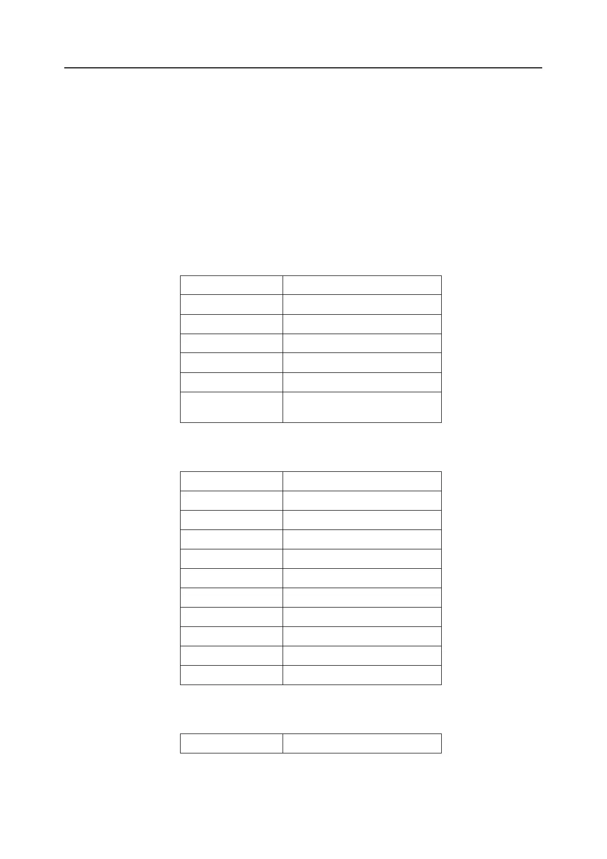
NCK alarms Table 1_1 Alarm number ranges
HMI alarms/messages Table 1_2 Alarm number ranges, continued
611D alarms Table 1_3 Alarm number ranges, continued
000 000 - 009 999 General alarms
010 000 - 019 999 Channel alarms
020 000 - 029 999 Axis/spindle alarms
030 000 - 099 999 Functional alarms
060 000 - 064 999 Cycle alarms SIEMENS
065 000 - 069 999 Cycle alarms user
070 000 - 079 999 Compile cycles, manufacturer and
OEM
100000 - 100999 Basic system
101000 - 101999 Diagnostics
102000 - 102999 Services
103000 - 103999 Machine
104000 - 104999 Parameter
105000 - 105999 Programming
106000 - 106999 Spare
107000 - 107999 OEM
109000 - 109999 Distributed systems (M to N)
110000 - 110999 HMI Embedded messages
120000 - 120999 HMI Advanced messages
300000 - 399999 Drive
 Loading...


