840D/828D SINUMERIK Operate Page 3
B507
B507
Notes
Section 2
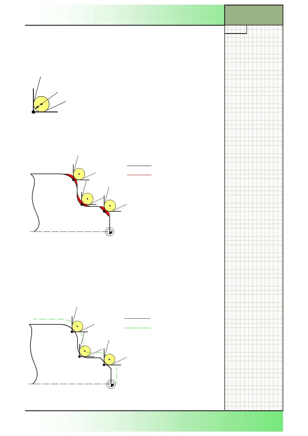
Tool nose radius correction
Workpiece is programmed as per the dimensions/coordinates described in
the drawing/CAD without taking any tool dimensions into account.
Due to the rounding of the tool nose there will, however, be a certain dis-
tance between the theoretical tool point “P” to the physical cutting edge.
R = Tip radius (tool nose radius)
S = Cutting edge centre point
P = Tool point (theoretical tool point)
A contour error will result on the surface of the work piece if in the program
a tool nose radius correction has not been activated
If the tool nose radius correction is activated, the cutting edge centre point
“S” will now be moved along an equidistant path parallel to the contour.
The equidistant path is parallel to the contour at a distance that equals the
cutting edge radius. Hence no contour errors will result.
Programmed contour
Resulting contour
Resulting contour
Equidistant path as
evaluated internally by
the control unit
P
S
R
 Loading...


