B523
B523 Page 38 840D/828D SINUMERIK Operate
Notes
Section 6
Zero offset basics
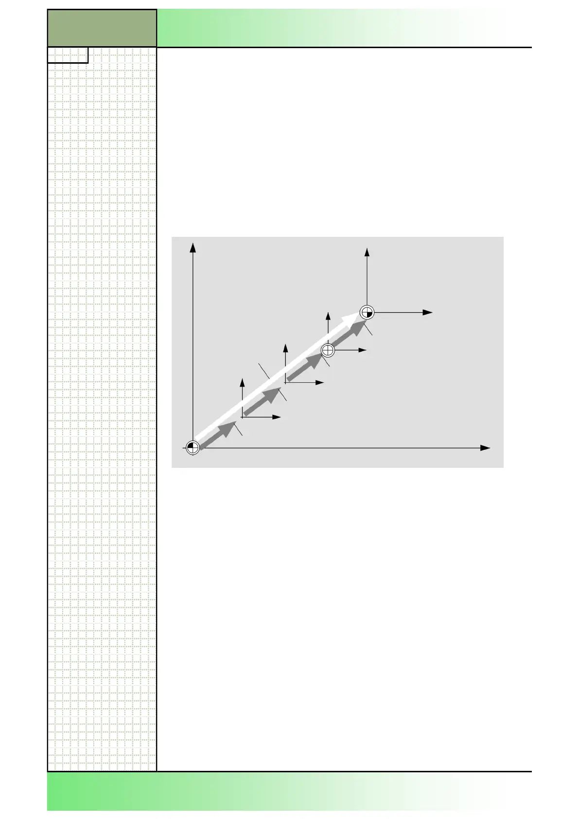
Following reference point approach, the actual value display for the axis
coordinates is based on the machine zero (M) of the machine coordinate
system (MCS ). The program for machining the workpiece, however, is
based on the workpiece zero (W) of the workpiece coordinate system
(WCS ).
The machine zero and workpiece zero are not necessarily identical.
The distance between the machine zero and workpiece vary in
accordance with the type of tool and the way it is clamped. This zero offset
is taken into account during execution of the program and can be a combi-
nation of different offsets.
In ShopMill, the position actual value display refers to the settable zero
system. The position of the active tool relative to the workpiece zero is dis-
played.
M
W
Machine
coordinate
system
WCS
Base offset
Work offset coarse
Tool offset
Work offset fine
Transformation of coordinates
SZS
Base offset
Zero offsets
The base offset is a zero offset that is always active.
If you have not defined a base offset, its value will be
zero. You determine the base offset via "Measure
workpiece zero” .
See Module B570 - ”Operating mode JOG”, “Set
Work offset” and “Measure workpiece zero”.
Every zero offset (G54 to G57, G505 to G599) con-
sists of a coarse offset and a fine offset. You can call
the work offsets from any sequence program (coarse
and fine offsets are added together).
You can save the workpiece zero, for example, in
the coarse offset,
and then store the offset that occurs when a new
workpiece is clamped between the old and the new
workpiece zero in the fine offset.




 To Next Page