840D/828D SINUMERIK Operate Page 5
B502
B502
Notes
Explanation:
For the determination of all points within the work space, the control unit
requires a zero point of the coordinate system. This has been determined
by the machine manufacturer. All other points have either fixed distances
from the machine zero point or else the distance must be defined.
The machine zero point (M) is determined by the
machine manufacturer and cannot be altered. On
milling machines it usually lies on the work table,
while on turning machines it is on the spindle flange.
The work piece zero point (W) is the origin of the
work piece coordinate system. This can be specified
by the programmer and should always be chosen in
a way that the least calculation work is required to
determine points on the contour given the dimen-
sioning of the drawing. For turning work it lies mostly
on the turning axis and the right hand planar face.
The reference point (R) is approached for initializ-
ing the path measuring system, which means that at
this point all axes are set to zero. This is necessary
since generally speaking the machine zero point
cannot be approached.
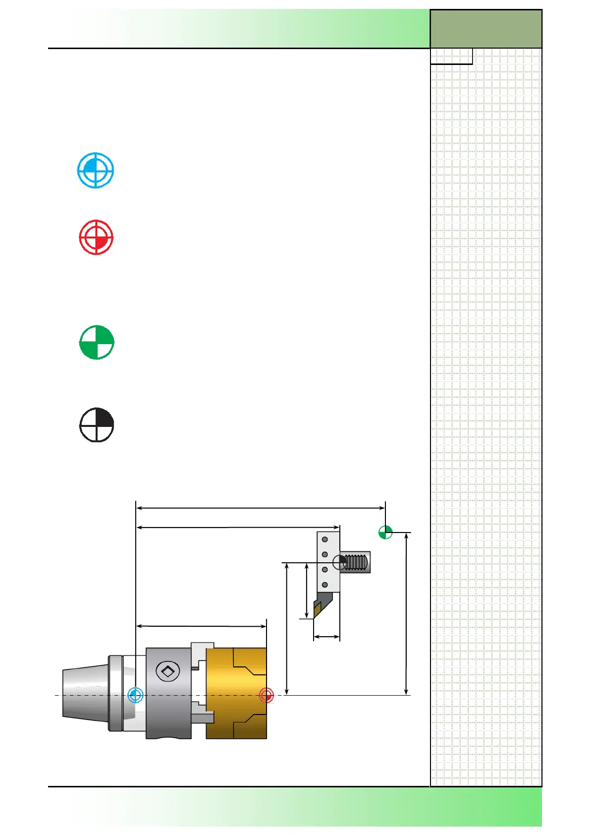
The tool carrier reference point (F) is of prime im-
portance for the adjustment of preset tools. The
lengths L (XPF) and offset O (ZPF) shown in the im-
age below are used as tool calculation values for
instance for the tool radius correction and must be
entered into the tool memory of the control unit.
ZMW
ZMR
ZMF
XMR
ZPF
XMF
XPF
Points and distances within the work space
Section 4
 Loading...


