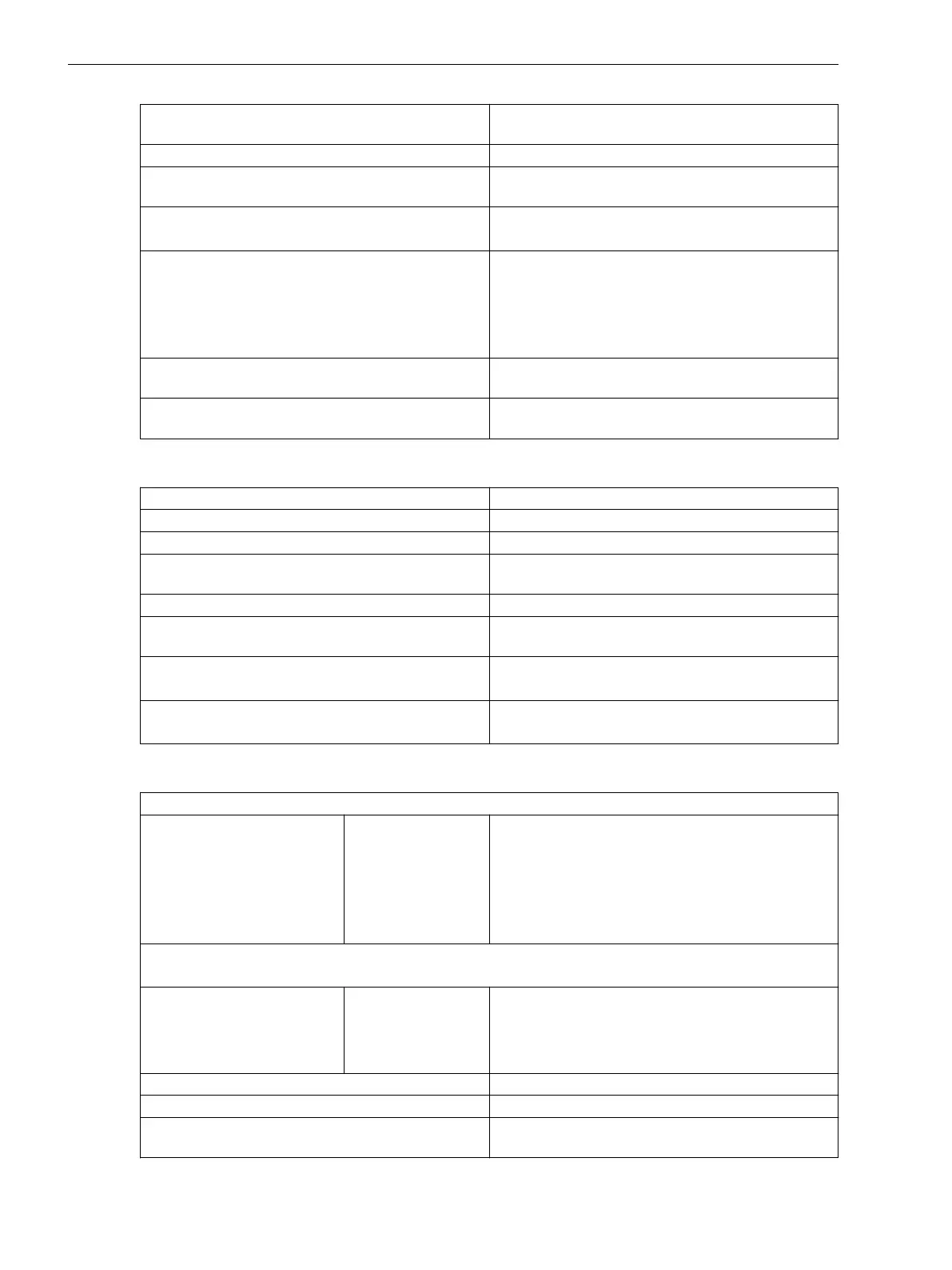
Permissible current per contact (switching on and
holding)
30 A for 1 s (make contact)
Short-time current across closed contact 250 A for 30 ms
Total permissible current for contacts connected to
common potential
5 A
Switching time OOT (Output Operating Time)
Additional delay of the output medium used
Make time: typical: 4 ms; maximum: 5 ms
Break time: typical: 2 ms; maximum: 5 ms
Rated data of the output contacts in accordance with
UL certification
AC 120 V, 5 A, General Purpose
AC 250 V, 5 A, General Purpose
AC 250 V, 0.5 hp
B300
R300
Interference suppression capacitors across the
contacts
4.7 nF, ± 20 %, AC 250 V
Supervision 2-channel activation with cyclic testing (only for make
contact)
High-Speed Relay with Semiconductor Acceleration (Type HS)
Switching capacity On/Off: 1000 W/VA
Contact voltage AC 200 V, DC 250 V
Permissible current per contact (continuous) 5 A
Permissible current per contact (switching on and
holding)
30 A for 1 s (make contact)
Short-time current across closed contact 250 A for 30 ms
Total permissible current for contacts connected to
common potential
5 A
Switching time OOT (Output Operating Time)
Additional delay of the output medium used
Make time, typical: 0.2 ms; maximum: 0.2 ms
Break time, typical: 9 ms; maximum: 9 ms
Rated data of the output contacts in accordance with
UL certification
B150
Q300
Power Relay (for Direct Control of Motor Switches)
Switching capacity for permanent and periodic operation
250 V/4.0 A
220 V/4.5 A
110 V/5.0 A
60 V/5.0 A
48 V/5.0 A
24 V/5.0 A
1000 W
1000 W
550 W
300 W
240 W
120 W
In order to prevent any damage, the external protec-
tion circuit must switch off the motor in case the rotor
is blocked.
Turn on switching power for 30 s, recovery time until switching on again is 15 minutes.
For short-term switching operations, an impulse/pause ratio of 3 % must be considered.
100 V/9.0 A
60 V/10.0 A
48 V/10.0 A
24 V/10.0 A
1000 W
600 W
480 W
240 W
Continuous and inching operation is not permitted.
In order to prevent any damage, the external protec-
tion circuit must switch off the motor in case the rotor
is blocked.
AC and DC contact voltage 250 V
Permissible continuous current per contact 5 A
Permissible current per contact (switching on and
holding)
30 A for 1 s
Technical Data
11.1 General Device Data
1110 SIPROTEC 5, High-Voltage Bay Controller, Manual
C53000-G5040-C015-A, Edition 05.2018

 Loading...


