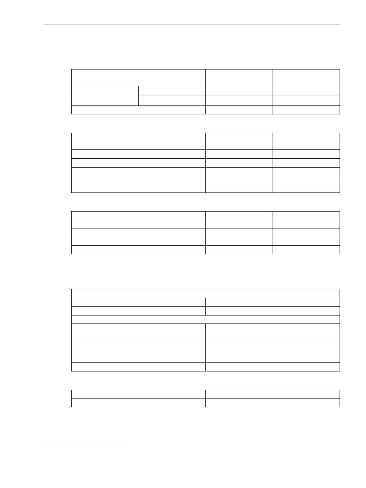
Voltage-Dependent Overcurrent Protection, Phases
Setting Values for All Stage Types
Method of measurement Fundamental component
RMS value
–
Overcurrent threshold
value
For I
rated
= 1 A 0.030 A to 35.000 A Increments of 0.001 A
For I
rated
= 5 A 0.15 A to 175.00 A Increments of 0.01 A
Time delay 0.10 s to 60.00 s Increments of 0.01 s
Setting Values for Inverse-Time Overcurrent Protection Stages
Method of measurement Fundamental component
RMS value
–
Dropout ratio of undervoltage
69
1.01 to 1.20 Increments of 0.01
Undervoltage threshold value
69
0.300 V to 175.000 V Increments of 0.001 V
Dropout Disk emulation
Instantaneous
–
Time multiplier 0.05 to 15.00 Increments of 0.01
Setting Values for Definite-Time Overcurrent Protection Stages
Seal-in voltage
0.300 V to 175.000 V Increments of 0.001 V
Phase-to-phase voltage 0.300 V to 175.000 V Increments of 0.001 V
Negative-sequence voltage V2 0.300 V to 200.000 V Increments of 0.001 V
Time delay 0.00 s to 60.00 s Increments of 0.01 s
Duration of V-seal-in time 0.10 s to 60.00 s Increments of 0.01 s
Dropout for Inverse-Time Overcurrent Protection Stages
The greater dropout differential (= | pickup value – dropout value |) of the following 2 criteria
applies:
Dropout
Current 95 % of 1.1 ⋅ threshold value
Voltage
69
105 % of threshold value
Minimum absolute dropout differential
Protection-class current transformer 15 mA sec. (I
rated
= 1 A) or
75 mA sec. (I
rated
= 5 A)
Instrument current transformer 0.5 mA sec. (I
rated
= 1 A) or
2.5 mA sec. (I
rated
= 5 A)
Voltage transformer
69
150 mV sec.
Reset of the Integration Timer for Inverse-Time Overcurrent Protection Stages
Instantaneous
With dropout
Disk emulation Approx. < 0.90 ⋅ threshold value
11.16
69
The value is for the inverse-time overcurrent voltage-released stage.
Technical Data
11.16 Voltage-Dependent Overcurrent Protection, Phases
SIPROTEC 5, High-Voltage Bay Controller, Manual 1165
C53000-G5040-C015-A, Edition 05.2018

 Loading...


