Up to 50th harmonic, f
rated
= 50 Hz 2 % of the setting value or 10 mA (I
rated
= 1 A)
or 50 mA (I
rated
= 5 A), (f
rated
± 10 %)
Up to 50th harmonic, f
rated
= 60 Hz 3 % of the setting value or 20 mA (I
rated
= 1 A)
or 100 mA (I
rated
= 5 A), (f
rated
± 10 %)
Currents, method of measurement = RMS value
with filter for the gain of harmonics (including compensation of the amplitude attenuation
42
(33 % harmonics, in relation to the fundamental component)
Up to 30 harmonic 1.5 % of the setting value or 10 mA (I
rated
= 1 A)
or 50 mA (I
rated
= 5 A), (f
rated
± 10 %)
43
Up to 50th harmonic, f
rated
= 50 Hz 3% of the setting value or 20 mA (I
rated
= 1 A)
or 100 mA (I
rated
= 5 A), (f
rated
± 10 %)
44
Up to 50th harmonic, f
rated
= 60 Hz 4 % of the setting value or 20 mA (I
rated
= 1 A)
or 100 mA (I
rated
= 5 A), (f
rated
± 10 %)
45
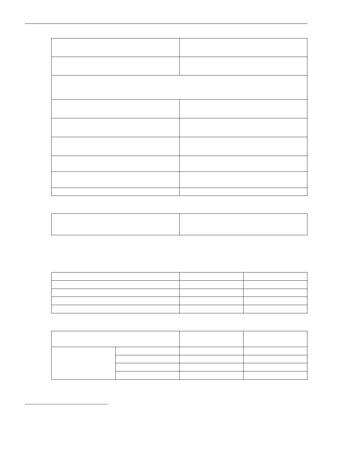
Operate time for 2 ≤ I/I threshold value ≤ 20 5 % of the reference (calculated) value
+2 % current tolerance or 30 ms
Dropout time for I/I threshold value ≤ 0.90 5 % of the reference (calculated) value
+2 % current tolerance or 30 ms
Time delays 1 % of the setting value or 10 ms
Influencing Variables for Thresholds
Transient excess pickup in method of measurement =
fundamental component, for τ > 100 ms (with
complete unbalance)
< 5 %
Stage with User-Defined Characteristic Curve
Setting Value for the Function Block Filter
h(0)
-100.000 to 100.000 Increments of 0.001
h(1) -100.000 to 100.000 Increments of 0.001
h(2) -100.000 to 100.000 Increments of 0.001
h(3) -100.000 to 100.000 Increments of 0.001
h(4) -100.000 to 100.000 Increments of 0.001
Setting Values for Protection Stage
Method of measurement
Fundamental component
RMS value
–
Threshold value 1 A @ 50 and 100 Irated 0.030 A to 35.000 A Increments of 0.001 A
5 A @ 50 and 100 Irated 0.15 A to 175.00 A Increments of 0.01 A
1 A @ 1.6 Irated 0.001 A to 1.600 A Increments of 0.001 A
5 A @ 1.6 Irated 0.005 A to 8.000 A Increments of 0.001 A
11.8.3
42
In case that the filter response exactly matches the user-defined gain factors
43
In case that the user-defined gain factor is set below 3. The tolerance increases, if the gain factor is larger.
44
In case that the user-defined gain factor is set below 7. The tolerance increases, if the gain factor is larger.
45
In case that the user-defined gain factor is set below 7. The tolerance increases, if the gain factor is larger.
Technical Data
11.8 Overcurrent Protection, Phases
1130 SIPROTEC 5, High-Voltage Bay Controller, Manual
C53000-G5040-C015-A, Edition 05.2018

 Loading...


