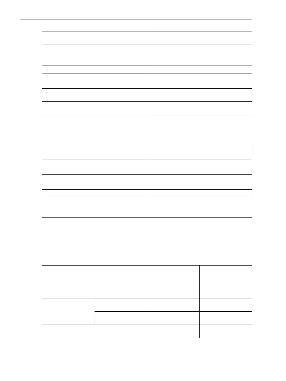
Extension of the operate time during operation with
transformer inrush-current detection
Approx. 10 ms
Dropout time Approx. 20 ms + OOT
Frequency Operating Range
0.9 ≤ f/f
rated
≤ 1.1 According to specified tolerances
10 Hz ≤ f < 0.9 f
rated
1.1 f
rated
< f ≤ 80 Hz
Slightly expanded tolerances
f < 10 Hz
f > 80 Hz
Active
Tolerances
Currents, method of measurement = fundamental
component
1 % of the setting value or 5 mA (I
rated
= 1 A)
or 25 mA (I
rated
= 5 A), (f
rated
± 10 %)
Currents, method of measurement = RMS value
(33 % harmonics, in relation to fundamental component)
Up to 30th harmonic 1 % of the setting value or 5 mA (I
rated
= 1 A)
or 25 mA (I
rated
= 5 A), (f
rated
± 10 %)
Up to 50th harmonic, f
rated
= 50 Hz 3 % of the setting value or 20 mA (I
rated
= 1 A)
or 100 mA (I
rated
= 5 A), (f
rated
± 10 %)
Up to 50th harmonic, f
rated
= 60 Hz 4 % of the setting value or 20 mA (I
rated
= 1 A)
or 100 mA (I
rated
= 5 A), (f
rated
± 10 %)
Time delay 1 % of the setting value or 10 ms
Direction-determination angle error 1 °
Influencing Variables for Thresholds
Transient excess pickup in method of measurement =
fundamental component, for τ > 100 ms (with
complete unbalance)
< 5 %
Stage with Inverse-Time Characteristic Curve
Setting Values
Rotation angle of the reference voltage
-180° to +180° Increments of 1°
Directional mode Forward
Backward
–
Method of measurement Fundamental component
RMS value
–
Threshold value
61
1 A @ 50 and 100 Irated 0.030 A to 35.000 A Increments of 0.001 A
5 A @ 50 and 100 Irated 0.15 A to 175.00 A Increments of 0.01 A
1 A @ 1.6 Irated 0.001 A to 1.600 A Increments of 0.001 A
5 A @ 1.6 Irated 0.005 A to 8.000 A Increments of 0.001 A
Dropout Disk emulation
Instantaneous
–
11.10.2
61
If you have selected the method of measurement = RMS value, do not set the threshold value under 0.1 l
rated,sec
.
Technical Data
11.10 Directional Overcurrent Protection, Phases
1144 SIPROTEC 5, High-Voltage Bay Controller, Manual
C53000-G5040-C015-A, Edition 05.2018

 Loading...


