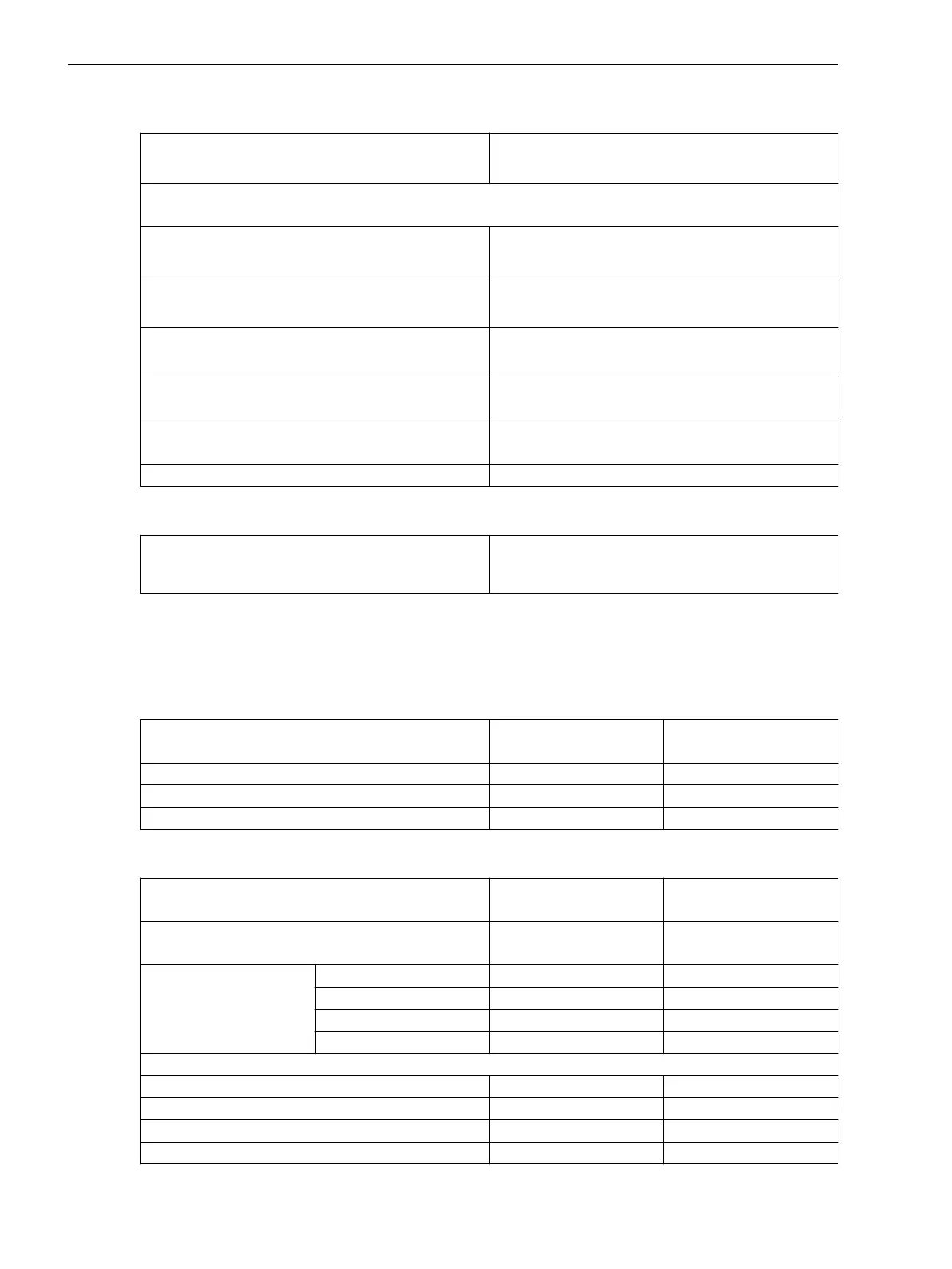
Tolerances
Currents, method of measurement = fundamental
component
1 % of the setting value or 5 mA (I
rated
= 1 A)
or 25 mA (I
rated
= 5 A)
Currents, method of measurement = RMS value
(33 % part of harmonic, referring to fundamental component)
Up to 30th harmonic 1 % of the setting value or 5 mA (I
rated
= 1 A)
or 25 mA (I
rated
= 5 A), (f
rated
± 10 %)
Up to 50th harmonic, f
rated
= 50 Hz 3 % of the setting value or 20 mA (I
rated
= 1 A)
or 100 mA (I
rated
= 5 A), (f
rated
± 10 %)
Up to 50th harmonic, f
rated
= 60 Hz 4 % of the setting value or 20 mA (I
rated
= 1 A)
or 100 mA (I
rated
= 5 A), (f
rated
± 10 %)
Operate time for 2 ≤ I/I threshold value ≤ 20 5 % of the reference (calculated) value
+ 2 % current tolerance or 30 ms
Dropout time for I/I threshold value ≤ 0.90 5 % of the reference (calculated) value
+ 2 % current tolerance or 30 ms
Direction-determination angle error 1º
Influencing Variables for Thresholds
Transient excess pickup in method of measurement =
fundamental component, for τ > 100 ms (with
complete unbalance)
< 5 %
Stage with Inverse-Time Overcurrent Protection with Logarithmic-Inverse
Characteristic Curve
Setting Values for the Function Direction Determination
Method for direction determination
Zero sequence
Negative sequence
–
Minimum V0 or V2 threshold 0.150 V to 20.000 V 0.001 V
Rotation angle of the reference voltage -180° to 180° 1°
Forward range 0° to 180° 1°
Setting Values
Direction mode
Forward
Reverse
–
Method of measurement Fundamental component
RMS value
–
Threshold value 1 A @ 50 and 100 Irated 0.030 A to 35.000 A Increments of 0.001 A
5 A @ 50 and 100 Irated 0.15 A to 175.00 A Increments of 0.01 A
1 A @ 1.6 Irated 0.001 A to 1.600 A Increments of 0.001 A
5 A @ 1.6 Irated 0.005 A to 8.000 A Increments of 0.001 A
Characteristic curve: see Figure 11-13
Threshold value multiplier 1.00 to 4.00 Increments of 0.01
Time multiplier 0.000 s to 60.000 s Increments of 0.001 s
Minimum time of the characteristic curve 0.000 s to 60.000 s Increments of 0.001 s
Maximum time of the characteristic curve 0.000 s to 60.000 s Increments of 0.001 s
11.11.3
Technical Data
11.11 Directional Overcurrent Protection, Ground
1152 SIPROTEC 5, High-Voltage Bay Controller, Manual
C53000-G5040-C015-A, Edition 05.2018

 Loading...


