The devices must be installed in switchgear cabinets with an adequate
degree of protection which takes the ambient conditions into account.
The products described herein are designed to be components of a customized
machinery safety-oriented control system. A complete safety-oriented system may
include safety sensors, evaluators, actuators and signaling components. It is the
responsibility of each company to conduct its own evalution of the effectiveness of the
safety system by trained individuals. SIEMENS AG, its subsidiaries and affiliates
(collectively "SIEMENS") are not in a position to evaluate all of the characteristics of a
given system or product or machine not designed by SIEMENS.
SIEMENS accepts no liability for any recommendation that may be implied or stated
herein. The warranty contained in the contract of sale by SIEMENS is the sole war-
ranty of SIEMENS. Any statements contained herein do not create new warranties or
modify existing ones.
You can use the safety relays 3TK2821/24 in EMERGENCY STOP devices as per
DIN EN / IEC 60947-5-5 and in safety circuits as per DIN EN / IEC 60204-1, e.g. with
movable covers and guard doors.
Using this device, max. Performance Level PL e / Cat. 4 according to
DIN EN ISO 13849-1 and/or SIL 3 according to DIN EN / IEC 62061 can be achieved.
Depending on the estimated risk, it may be necessary to carry out additional measu-
res in the sensor circuit (e.g. shielded cable laying). When 3TK 2821/24 is used as a
contact extension, the PL / Cat. / SIL that can be achieved is the same as for the
basic device. The user must carry out an evaluation of the overall systems.
Safety relay 3TK2821 has three release circuits (safety circuits) which are configured
as NO circuits and a signal circuit configured as an NC circuit.
Safety relay 3TK2824 has two release (safe) circuits which are configured as NO cir-
cuits. The number of release circuits can be increased by adding one or more
3TK2830 extension modules. Three LEDs indicate the operating state and function.
When the EMERGENCY STOP button or the limit switch is unlocked and when the
ON button is pressed, the internal circuits of the safety relay and the external contac-
tors are checked for proper functioning.
Connect the EMERGENCY STOP pushbutton or the limit switch in the supply cable
from A1 to +24 or L24 V. To evaluate over two channels, connect Channel 2 from A2
to 0 V or N. Connect the ON button in series with the NC contacts of the external con-
tactor (feedback circuit) to terminals Y1 and Y2 (for circuit examples, see Figs. V to
VIII).
Be sure to fit the specified fuses. Otherwise safe interruption in the
event of a fault cannot be guaranteed.
For further data and accessories see Catalog.
Read and understand these instructions before installing,
operating, or maintaining the equipment.
DANGER
Hazardous voltage.
Will cause death or serious injury.
Turn off and lock out all power supplying this device before working
on this device.
CAUTION
Reliable functioning of the equipment is only ensured with certified
components.
IMPORTANT NOTICE
Application
Functions and connections
Terminal
assignments
Operating
voltage
A1
A2
L/+
N/
–
Sensors Y1, Y2 ON button, feedback circuit
Outputs 13, 14
23, 24
33, 34
41, 42
Release circuit 1 (NO)
Release circuit 2 (NO)
Release circuit 3 (NO)*
Signal circuit (NC)*
*) with 3TK2821 only
Cable lengths for 2 x 1.5 mm
2
max. 1000 m (total cable length for
sensors and power supply lines)
Figures Fig. I: Dimension drawings (dimensions in mm)
Fig. II: Installation / spring loaded terminal
Fig. IIIa: Safety data
Fig. IIIb: Application data
Fig. IV: Internal circuit: ¿ PTC fuse, À power pack,
Á control logic, Â Channel 1, Ã Channel 2
Fig. V: EMERGENCY STOP, single-channel
Fig. VI: EMERGENCY STOP, two-channel
Fig. VII: Guard door monitoring, single-channell
Fig. VIII: Guard door monitoring, two-channel
Fig. IX: 3TK2821 as a contact extension
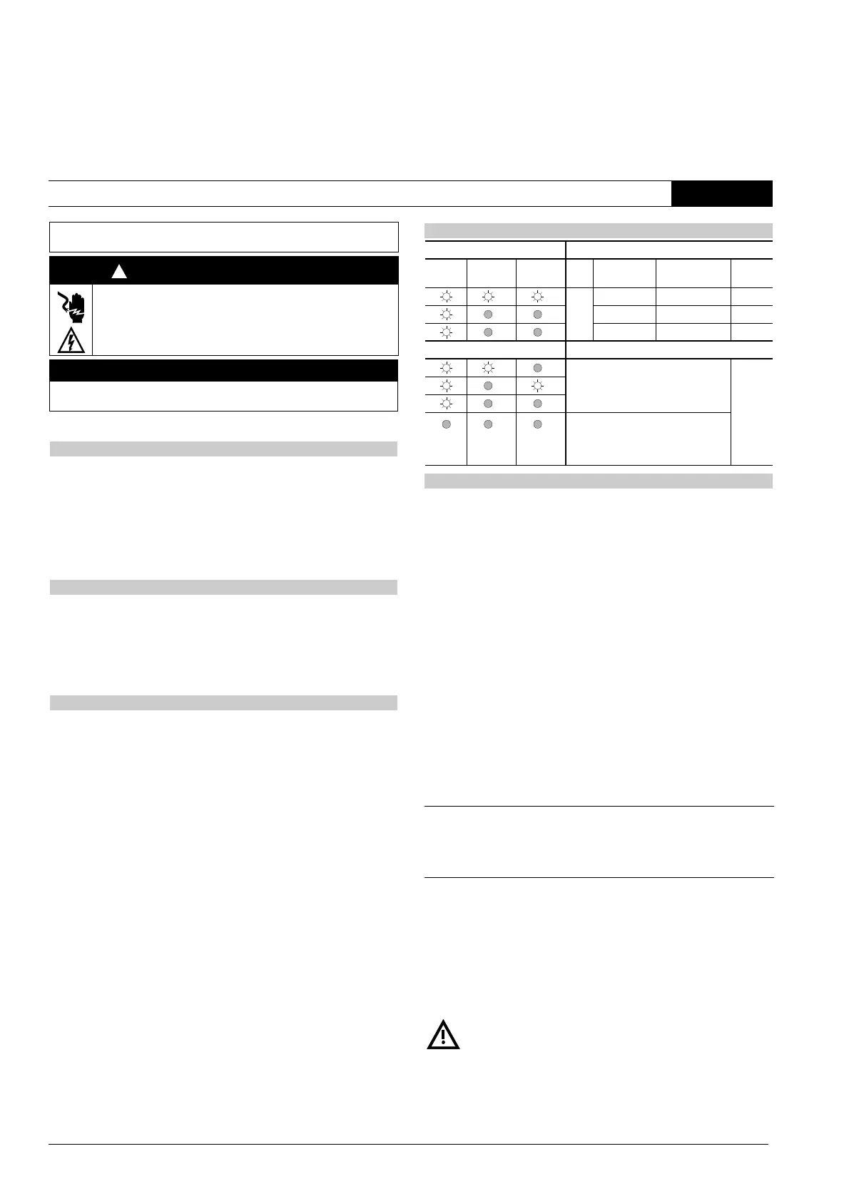
Operating states
LEDs Operation
POWER Channel 1 Channel 2 PS EMERGENC
Y STOP
ON Release
circuits
ON not activated was activated closed
activated not activated open
not activated not activated open
Faults
• Relay fusion-welded
• Motor contactor fusion-welded
• Defect in electronics
open
Cross or ground faults in EMERGENCY
STOP circuit (min. fault current I
Kmin
=
0.5 A; PTC fuse trips) or supply voltage
missing
Technical data
Permissible ambient temperature T
u
Operation/storage –25 to +60 °C / –40 to +80 °C
Degree of protection to DIN EN / IEC 60529 IP40, IP20 at terminals
Rated insulation voltage U
i
300 V
Rated impulse withstand voltage U
imp
4kV
Rated control supply voltage U
s
24 V AC / DC
Rated power 1.5 W
DC operating range
0.85 to 1.2 x U
s
AC operating range
0.85 to 1.1 x U
s
Shock resistance 8 g / 10 ms
Weight 0.240 kg
Recovery time min. 200 ms (DC) / 300 ms (AC)
Release time max. 200 ms
Response time max. 150 ms
Utilization category
as per VDE 0660-200,
DIN EN / IEC 60947-5-1
Rated operational
voltage U
e
(V)
Rated operational current I
e
with all release circuits loaded
(A)
50 °C 60 °C 70 °C
AC-15 230 5 4.5 4
DC-13 24 5 4.5 4
115 0.2 0.2 0.2
230 0.1 0.1 0.1
Continuous current I
th
54.54
Short-circuit
protection
Fuse links DIAZED
for release circuit Duty class gL (gG) 6 A / quick response 10 A
and signal circuit Duty class gL (gG) 6 A / quick response 6 A
or SITOP select Diagnostics Module (Order No.: 6EP1961-2BA00)
for enabling circuits
and signaling circuits
Please adhere to the respective user information!
(Order No.: C98130-A7524-A1-05-7419)
SIRIUS 3TK2821, 3TK2824
Safety Relay
DIN EN / IEC 60947-5-1
Operating Instructions Order No.: 3ZX1012-0TK28-1CA1
English
2
 Loading...