EasyManua.ls Logo

Siemens SITOP 6EP1961-2BA21 User Manual

Siemens SITOP 6EP1961-2BA21
58 pages
To Next Page IconTo Next Page
Page #1 background imageLoading...
Page #1 background image
Selectivity modules
___________________
___________________
___________________
___________________
___________________
___________________
___________________
___________________
___________________
___________________
___________________
SITOP power supply
Selectivity modules
Manual
SITOP select
6EP1961
-2BA00
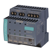
SITOP PSE200U 3A
6EP1961
-2BA11
SITOP PSE200U 10 A
6E
P1961-2BA21
SITOP PSE200U 3 A
6EP1961
-2BA31
SITOP PSE200U 10 A
6EP1961
-2BA41
12.2014
C98130
-A7579-A1-1-7629
Overview
Safety notes
1
Description, device design,
dimension drawing
2
Mounting/removal
3
Mounting position, mounting
clearances
4
Installation
5
Technical data
6
Safety, approvals, EMC
7
Environmental conditions
8
Environment
9
Service & Support
10
Question and Answer IconNeed help?

Do you have a question about the Siemens SITOP 6EP1961-2BA21 and is the answer not in the manual?

Siemens SITOP 6EP1961-2BA21 Specifications

General IconGeneral
Output Voltage24 V DC
Output Current10 A
Power240 W
Weight1.2 kg
Protection ClassIP20
Dimensions125 mm x 80 mm x 120 mm

Summary

Safety notes

Description, device design, dimension drawing

Device description

Details the physical attributes and components of the SITOP selectivity modules.

Connections and terminal designation

Explains the purpose and type of each terminal connection on the devices.

Status displays and signaling

Covers the LEDs and signal outputs used for monitoring device and output status.

Electronic overload shutdown and reset

Explains how the module protects against overload by shutting down outputs and how to reset them.

Setting the switch-on delay time

Guides on configuring the time delay for sequential output switching to manage inrush currents.

Mounting/removal

Installation

Input side connection

Instructions for connecting the 24 V DC power supply to the input terminals of the module.

Output-side connection

Guidance on connecting the loads to the output terminals of the selectivity modules.

Technical data

Input

Specifies electrical parameters for the DC input voltage and range.

Output

Lists electrical characteristics of the outputs, including voltage, current, and number of outputs.

Related product manuals