Do you have a question about the Siemens SITOP series and is the answer not in the manual?
Guidelines for safe operation and handling of electrical devices to prevent injury and damage.
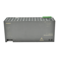
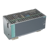
Detailed explanation of the SITOP modular power supply's features and functionality.
Information on input and output terminals, including their designations and connection data.
Details on setting the output voltage using the front panel potentiometer.
Explanation of the LEDs and their meaning for device status and operation.
How the A/B switches affect output characteristics like parallel operation and shutdown.
Schematic representation of the internal functional blocks of the power supply.
Physical dimensions and weight for various SITOP modular power supply models.
Guidelines for vertical mounting on standard rails and required clearances for cooling.
Derating factors for mounting positions deviating from the standard setup.
Instructions for connecting the power supply to the AC line supply, including protection devices.
Guidance on connecting the output terminals to the load, ensuring proper cable sizing and fusing.
Details on rated voltage, voltage range, wide-range input, and input current.
Specifications for regulated DC voltage, tolerances, ripple, and current ratings.
Data on the device's efficiency at rated load and power loss under various conditions.
Information on output overvoltage protection, current limitation, and overload display.
Housing dimensions, mounting types, and weight for the SITOP modular units.
How to connect multiple units in parallel to achieve higher output power ratings.
Using modules to connect power supplies in parallel for increased system availability.
Connecting units in series to achieve higher output voltages.
Methods for protecting the 24V output circuit against overloads and short-circuits.
Using buffer modules to maintain output voltage during short-time line supply interruptions.
Contact information and resources for obtaining technical assistance and product information.
Information on finding local Siemens sales contacts and partners for support.
| Output Current | 40 A |
|---|---|
| Power Rating | 960 W |
| Operating Temperature | -25°C to +70°C |
| Protection | Overload, short circuit, overtemperature |
| Mounting | DIN rail |
| Series | SITOP PSU100 |
| Communication | PROFINET |
| Redundancy | Optional |
| Cooling Method | Convection cooling, some models may have forced air cooling |
| Certifications | UL, CE, cULus, ATEX, IECEx |





 Loading...