Do you have a question about the Siemens SITRANS P200 and is the answer not in the manual?
Provides essential guidelines for the proper installation of the pressure transmitter.
Explains the meaning of the warning symbol found on the device.
Outlines critical safety notes for operating the device, including directives and intrinsic safety.
Illustrates wiring configurations for different plug and cable types for current and voltage outputs.
Shows specific wiring for devices with explosion protection.
Specifies installation conditions for intrinsically safe devices in hazardous areas.
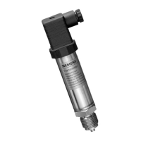
The SITRANS P200 (7MF1565) is a pressure transmitter designed for measuring relative and absolute pressure of gases and liquids across various industrial sectors. Its robust construction and versatile connection options make it suitable for a wide range of applications, including mechanical engineering, power engineering, water supply, shipbuilding, chemicals, and pharmaceuticals.
At its core, the SITRANS P200 utilizes a piezoresistive measuring cell with a diaphragm, housed within a durable stainless steel casing. This advanced sensing technology allows for precise and reliable pressure measurement. The diaphragm, in contact with the process medium, deforms under pressure, and this deformation is converted into an electrical signal by the piezoresistive elements. This electrical signal is then processed to provide a standardized output, either 4 to 20 mA or 0 to 10 V, which can be easily integrated into control systems.
The device is designed to operate within a specified range of pressures, with built-in overload limits and burst pressure ratings to ensure safety and longevity. It offers high accuracy, with minimal deviation at standard temperatures, and exhibits excellent long-term stability, reducing the need for frequent recalibration. The transmitter's performance is also robust against environmental factors such as ambient temperature fluctuations and vibrations, making it suitable for demanding industrial environments.
For applications requiring intrinsic safety, specific models of the SITRANS P200 are available. These models are designed to prevent ignition in hazardous areas by limiting the electrical energy available to the device, ensuring safe operation in potentially explosive atmospheres. When used in such environments, the grounding connection is conductively linked to the transmitter housing, providing an additional layer of safety.
The SITRANS P200 offers flexible electrical connection options to suit different installation requirements. It can be connected via a plug complying with EN 175301-803-A (IP65), a round plug M12 (IP67), a direct cable connection (IP67), or a fast-fit cable gland (IP67). These options ensure secure and reliable electrical integration into various systems, with high degrees of ingress protection against dust and water.
Installation of the device is straightforward, and its location does not significantly impact the precision of the measurement. However, it is crucial to compare the process data with the device's nameplate data before installation to ensure compatibility. The medium being measured must be suitable for the materials of the pressure transmitter that come into contact with the medium, primarily the measuring cell (Al2O3 - 96%) and the process connection (stainless steel, material no. 1.4404). Various sealing materials, such as Viton (FPM), Neoprene (CR), Perbunan (NBR), and EPDM, are available to accommodate different media temperatures and chemical compatibilities.
For intrinsically safe versions, the device must be connected to certified intrinsically-safe resistive circuits with specified maximum values for voltage, current, and power. The grounding of the pressure transmitter is essential and must be connected to the equipotential bonding system of the plant via the metal housing (process connection) and the ground conductor of the plug. This ensures proper electrical safety and performance.
The device is designed for continuous operation and provides a linear rising output characteristic, making it easy to interpret the measured pressure. It has a fast setting time, ensuring quick response to pressure changes. The robust construction, including a stainless steel housing and durable connector materials, ensures a long service life even in harsh industrial conditions.
One of the key advantages of the SITRANS P200 is its maintenance-free design. Once installed and properly configured, the transmitter requires no routine maintenance, significantly reducing operational costs and downtime. This is due to its robust construction, high-quality components, and stable measurement performance.
While the device itself is maintenance-free, it is recommended to periodically check the start-of-scale value to ensure continued accuracy. This check helps confirm that the transmitter is operating within its expected parameters and that no significant drift has occurred over time.
The transmitter is factory-preset to the specific measuring range, and no additional setting for zero point or span is possible by the user. This simplifies commissioning and ensures consistent performance as per manufacturer specifications.
In the event of any issues or for technical support, Siemens provides comprehensive assistance through various channels, including online support requests, email, phone, and fax. This ensures that users can quickly resolve any queries or problems they might encounter during the device's lifespan. The date of manufacture, visible on the device label, provides important information for traceability and support.
| Type | Pressure transmitter |
|---|---|
| Output Signal | 4 to 20 mA, HART |
| Communication Protocol | HART |
| Measured Medium | Liquids and gases |
| Temperature Range (Operating/Ambient) | -40 to 85 °C |
| Process Connection | G1/2, 1/2" NPT, others available |
| Housing Material | Stainless steel |
| Protection Class | IP67 |