G
Gabriela LeeSep 23, 2025
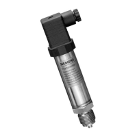
What to do if Siemens SITRANS P320 shows INVALID CFG PARAM?
- DDustin MunozSep 23, 2025
If your Siemens Transmitter shows INVALID CFG PARAM, it indicates that the factory settings for Functional Safety are faulty. Replace the device.