Document No. 129-400
Installation Instructions
October 2, 2009
Page 2 of 5 Siemens Industry, Inc.
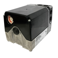
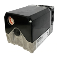
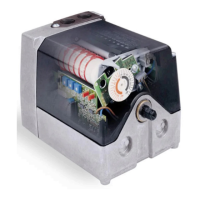
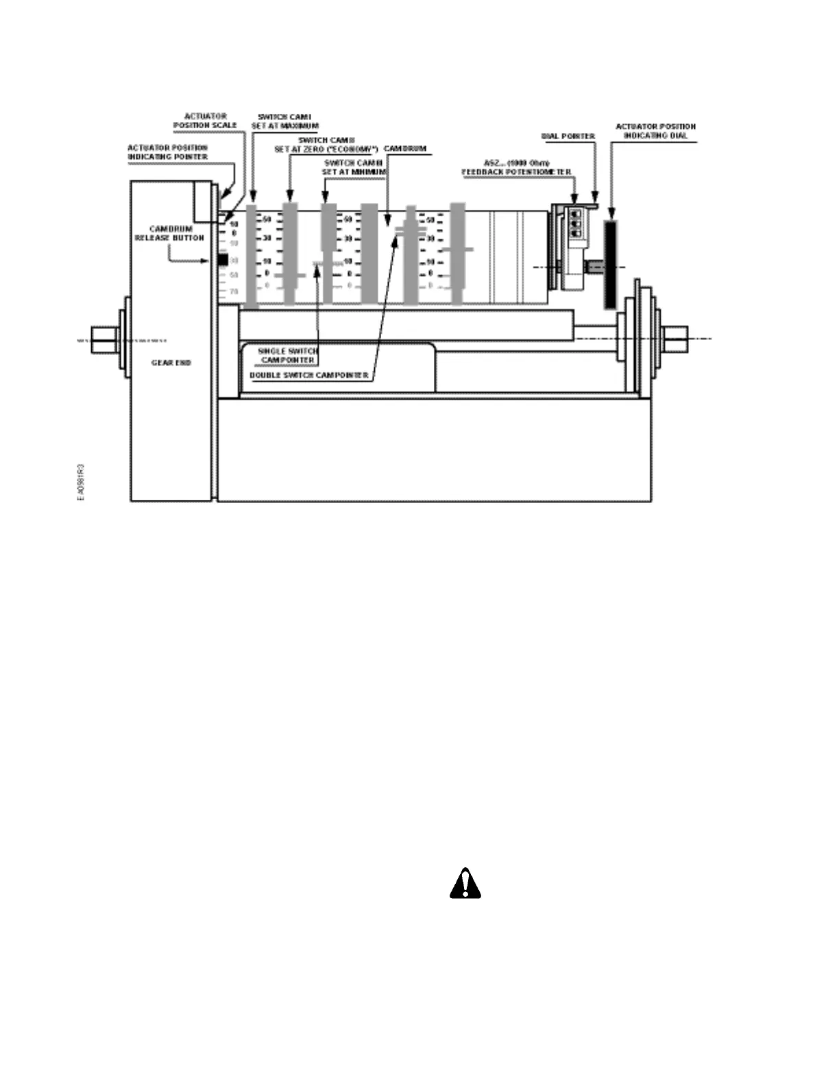
Figure 3. Component Identification on the Cam Drum Side of the SQM5…Actuator.
NOTE: The single switch cam pointers are used
together with the black scales when
configured for ccw operation.
The double switch cam pointers are used
together with the red scales when configured
for cw operation.
The individual switch cams can be adjusted
by hand or with the use of the tool attached to
the outside of the hinged switch terminal
protection lid.
The adjustable range of the switches is limited
by the potentiometer range.
SQM5x.xxxRxx3 actuators have a 90°
potentiometer and the switches must be
adjusted between 0° and 90°.
SQM5x.xxxRxx4 actuators have a 135°
potentiometer and the switches must be
adjusted between 0° and 135°.
Shaft Adjustment
The actuator shaft can be disengaged by pressing the
silver shaft release button. The shaft release button is
located above the grounding screw, under the hinged
terminal protection cover, and to the right of the
auto/manual switch. After pressing the shaft release
button in and slightly upward, the shaft can be
manually rotated. After the shaft has been manually
aligned to the closed position, re-engage the shaft
by pushing the shaft release button downwards.
Cam Drum Adjustment
Once the shaft has been set to the closed position,
the cam drum must be manually aligned by
pressing and holding the black cam drum release
button (see Figure 3). Rotate the cam drum until
the “0” mark on the actuator position scale (left
scale on the cam drum) is aligned with the gray
actuator position indicating pointer.
Position Indicating Dial Adjustment
The actual position of the SQM5… actuator is
indicated by the gray actuator position indicating
pointer (see Figure 3). The position is also
displayed by the indicating dial through the
housing’s window. Ensure that the actuator position
indicating dial is aligned with the actuator position
scale. If necessary, rotate the dial in the clockwise
direction.
Turning the dial in the counterclockwise
direction may loosen the potentiometer
locking screw.
 Loading...